Piston of rotary compressor and rotary compressor with same and multistage compressor with same

A rotary compressor and piston technology, applied in the field of compressors, can solve the problems of complex design process and assembly process, increase the eccentric inertial force of the crankshaft, and influence the reliability of the compressor, and achieve weight reduction, reduction of the rotating eccentric inertial force, Vibration and noise reduction effect

Inactive Publication Date: 2015-09-23
GUANGDONG MEIZHI COMPRESSOR +1
View PDF5 Cites 2 Cited by
  • Summary
  • Abstract
  • Description
  • Claims
  • Application Information

AI Technical Summary

Problems solved by technology

However, adding balance weights not only increases the cost, but also makes the design process and assembly process much more complicated
In addition, the increase in the mass of the balance weight will also increase the eccentric inertial force of the crankshaft, increase the inertial force when the compressor is running, and increase the wear of the crankshaft, which will affect the reliability of the compressor.

Method used


Image

  • Piston of rotary compressor and rotary compressor with same and multistage compressor with same
  • Piston of rotary compressor and rotary compressor with same and multistage compressor with same
  • Piston of rotary compressor and rotary compressor with same and multistage compressor with same

Examples


Embodiment 1

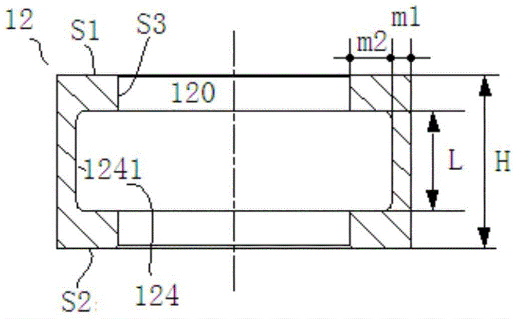
[0050] In this example, if image 3 As shown, the groove 124 in the piston 12 includes a sub-groove 1241 .

[0051] Specifically, the sub-groove 1241 is arranged around the central hole 120, and the sub-groove 1241 is annular, that is, the inner wall surface S3 of the central hole 120 is provided with one sub-groove 1241 along the entire circumference, which reduces the weight of the piston 12 to the greatest extent. , the purpose of reducing the inertial force of the eccentric portion 62 is achieved.

[0052] Wherein, when the axial height L of the groove 124 is too large, it is impossible to ensure that the inner wall surface S3 of the central hole of the piston 12 is fully in contact with the outer peripheral wall of the eccentric part of the crankshaft 6, and when the axial width L of the groove 124 is too small, The effect of the groove 124 on the eccentric balance of the eccentric component is not obvious, therefore, the axial height L of the groove 124 needs to be rest...

Embodiment 2

[0056] In this example, if Figure 4 As shown, the structure of the piston 12 is substantially the same as the structure of the piston 12 in Embodiment 1, and will not be repeated here.

[0057] The difference is that, in the second embodiment, the groove 124 in the piston 12 includes a plurality of sub-grooves 1241 , that is, the number of sub-grooves 1241 is 2 or more.

[0058] Specifically, the groove 124 includes a plurality of annular sub-grooves 1241 arranged at intervals along the axial direction of the central hole 120 . In this way, the part between two adjacent sub-grooves 1241 constitutes the reinforcing rib 1242 , thereby increasing the structural strength of the piston 12 on the premise of reducing the weight of the piston 12 and ensuring that the piston 12 is not easily deformed.

[0059] When there are multiple sub-grooves 1241 , the axial height L of the groove 124 is the sum of the axial heights of the plurality of sub-grooves 1241 . Wherein, the axial heigh...


PUM


Abstract

The invention discloses a piston of a rotary compressor and a rotary compressor with the same and a multistage compressor with the same. The piston is integrally formed, a central hole is formed in the piston, grooves are formed in the inner wall face of the central hole, and the two sides of the grooves are separated from the two end faces of the piston. According to the piston of the rotary compressor, machining and assembling are facilitated, the weight of the piston is reduced, the eccentric rotating inertia force of the rotary compressor with the piston is reduced, the weight of balance weights in the compressor can be reduced conveniently, the vibration and noise of the compressor are reduced at the same time, the reliability of the compressor for operating for a long time is improved, and the problem that performance is reduced due to leakage of coolant in an exhaust vent can be effectively prevented.

Description

technical field [0001] The invention relates to the field of compressors, in particular to a piston of a rotary compressor, a rotary compressor and a multistage compressor with the same. Background technique [0002] For rotary compressors, the main working part is the rolling piston nested on the eccentric crankshaft. When the compressor motor is powered on, the eccentric crankshaft connected to the motor rotor will drive the rolling piston to do eccentric movement in the compression chamber of the pump body. Thereby realizing the compression of the refrigerant gas. This type of mechanism is widely used in various refrigeration equipment technical fields due to its simple structure and high compression efficiency. [0003] Due to the eccentric rotation structure, the center of gravity of the moving parts is not on the rotating shaft, so the compressor will generate a rotational inertial force when it is running, and its direction points to the eccentric direction. The exi...

Claims


Application Information

Patent Timeline
IPC IPC(8): F04C29/00F04C18/356
Inventor 吴灏方智祥
Owner GUANGDONG MEIZHI COMPRESSOR
Why Eureka
Try Eureka