
Continuous variable transmission

A continuously variable transmission and input shaft technology, applied to transmission parts, belts/chains/gears, mechanical equipment, etc., can solve problems such as excess lubricating oil, poor efficiency, etc., and achieve the effect of reducing friction

Active Publication Date: 2015-09-23
HONDA MOTOR CO LTD
View PDF8 Cites 0 Cited by
  • Summary
  • Abstract
  • Description
  • Claims
  • Application Information

AI Technical Summary

Problems solved by technology

[0005] However, the amount of oil discharged by a general oil pump is proportional to the engine speed, and the inertial force of the connecting rod is proportional to the square of the engine speed. (When the transmission ratio is OD) and the low vehicle speed condition with a small eccentricity (when the transmission ratio is UD), the amount of lubricating oil supplied becomes redundant (refer to Figure 8B )
The excess lubricating oil acts as agitation resistance of the bearing and deteriorates the efficiency

Method used


Image

  • Continuous variable transmission
  • Continuous variable transmission
  • Continuous variable transmission

Examples


Embodiment Construction

[0027] Hereinafter, embodiments of the present invention will be described in detail with reference to the drawings. In addition, the embodiment described below is an example of the means for realizing the present invention, and the present invention can be applied to a configuration in which the following embodiment is modified or modified within a scope not departing from the gist. In addition, it is self-evident that the continuously variable transmission of the present invention can also be applied to other applications than automobiles.

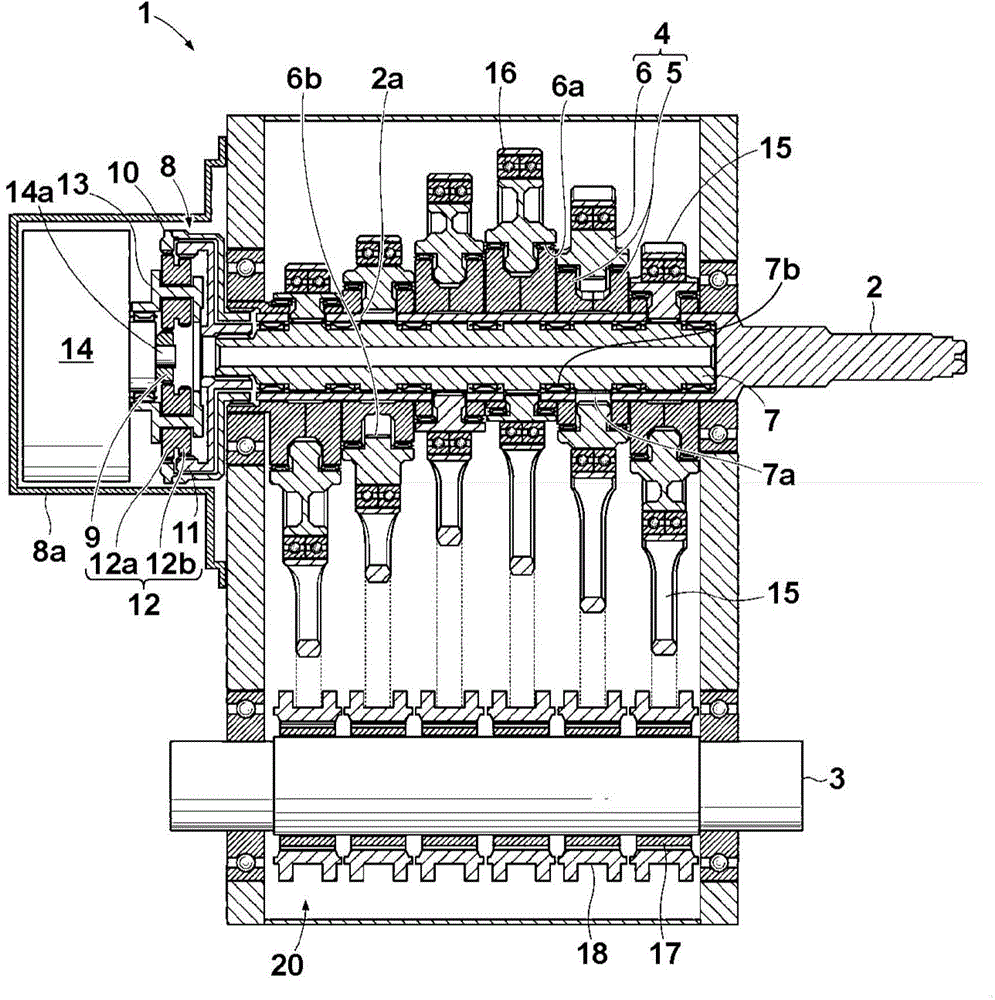
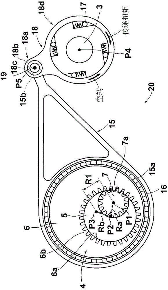
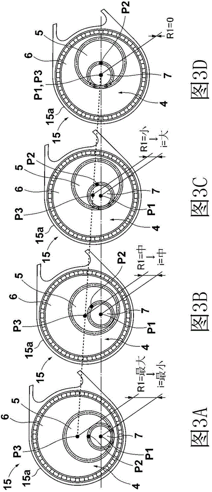
[0028] First, refer to figure 1 with figure 2 The structure of the continuously variable transmission of this embodiment will be described.

[0029] The continuously variable transmission 1 of the present embodiment is a transmission capable of setting the gear ratio i (i = the rotation speed of the input shaft / the rotation speed of the output shaft) to infinity (∞) and the rotation speed of the output shaft to "0", namely A kind of so-ca...


PUM


Abstract

The invention provides a continuous variable transmission. The continuous variable transmission is provided with an oil path penetrating through a part of an accommodating hole (6a) of an eccentric part (6) outwardly from the internal periphery. The oil path (3) is provided with an inlet hole (33a) supplying lubricating oil from the accommodating hole (6a) of the eccentric part (6); and an outlet hole (33b) discharging lubricating oil to the external. At least the outlet hole (33b) of the oil path of the oil path (33) is arranged on an extension line (Ra1) of a line (Ra) connecting the rotation center (P1) of an input shaft and the center (P2) of a cam part (5) when a specific eccentric volume (R1(R10<=R1<=R1max)) is adjusted through an eccentric volume adjusting mechanism (8-14). The specific eccentric volume (R1) is corresponding to a transmission ratio (TD) of the maximum speed when a vehicle is moving on a flat road.

Description

Technical field [0001] The invention relates to an oil supply structure of a continuously variable transmission of a four-section link mechanism type. Background technique [0002] For example, Japanese Patent Laid-Open No. 2012-1048 describes the following four-section link mechanism continuously variable transmission, which converts the rotation of the input shaft connected to the engine into the reciprocating motion of the connecting rod, and connects the transmission through a one-way clutch. The reciprocating movement of the rod is converted into the rotational movement of the output shaft. [0003] The above-mentioned four-section link mechanism type continuously variable transmission is provided with an oil passage that penetrates from the inner periphery to the outer periphery of the eccentric disc. The lubricating oil supplied to the center shaft hole of the input shaft by the oil pump is generated by centrifugal force accompanying the rotation of the input shaft It is pr...

Claims


Application Information

Patent Timeline
Patent Type & Authority Applications(China)
IPC IPC(8): F16H57/04
CPCF16H21/20F16H57/043F16H57/0431F16H57/0434
Inventor 西村优史
Owner HONDA MOTOR CO LTD
Learn More