Sealing structure for high temperature revolution equipment and static equipment, and use method of same

A sealing structure and equipment technology, applied in lighting and heating equipment, rotary drum furnace, furnace, etc., can solve problems such as heat loss

Inactive Publication Date: 2015-09-23
SHENYANG ALUMINIUM MAGNESIUM INSTITUTE
View PDF8 Cites 4 Cited by
  • Summary
  • Abstract
  • Description
  • Claims
  • Application Information

AI Technical Summary

Problems solved by technology

Due to structural reasons, the sealing device of the previous cooler could not

Method used


Image

  • Sealing structure for high temperature revolution equipment and static equipment, and use method of same

Examples


Embodiment Construction

[0019] The present invention will be described in further detail below in conjunction with the accompanying drawings, but the protection scope of the present invention is not limited by the implementation examples.

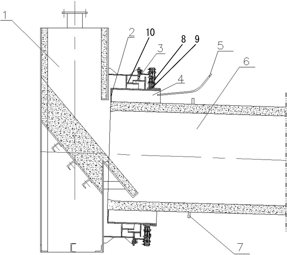
[0020] Such as figure 1 As shown, the sealing structure of high-temperature rotary equipment and static equipment of the present invention mainly includes: static equipment 1, rotary ring I2, stationary ring 3, gap between rotary ring I and cylinder body 4, water pipe 5, rotary equipment 6, water retaining ring 7 , sealing device 8, sealing ring 9, slewing ring II 10, etc., the specific structure is as follows:

[0021] A sealing device 8 is installed between the rotary device 6 and the static device 1 of the cooler, a static ring 3 is installed on one side of the static device 1, a sealing device 8 is installed on one end of the static ring 3, and a rotary ring I2 is installed outside one end of the rotary device 6. The sealing device 8 forms a sealing engagemen...


PUM


Abstract

The invention relates to the production field of alumina and concretely relates to a sealing structure for high temperature revolution equipment and static equipment, and a use method of the same. The sealing structure can prevent a sealing device used in a sealed connection part between the high temperature revolution equipment and the static equipment losing efficacy due to thermal formation caused by high temperature. The sealing structure comprises the static equipment, the revolution equipment, revolution rings, a water pipe, a sealing structure, a sealing device and a cylinder gap, wherein the cylinder bottom part of the revolution ring (I) is connected with the revolution equipment; a gap is formed between a cylinder body part of the revolution ring (I) and a cylinder body of the revolution equipment; one end of the pressurized water pipe extends into the gap; cooling water can be injected to the gap by the pressurizing water pipe; the external side of the revolution ring (I) is provided with a revolution ring (II); and a gap is reserved between the revolution ring (II) and a static ring. A certain gap is reserved between the sealing device and the cylinder body of the revolution equipment and the cylinder body can be sprayed by the water pipe, so thermal deformation of the sealing device due to excessive high temperature of the cylinder body can be avoided and sealing effect can be maintained.

Description

technical field [0001] The invention relates to the field of alumina production, in particular to a sealing structure and usage method of high-temperature rotary equipment and static equipment. Its function is to prevent the seal joint between high-temperature rotary equipment and static equipment from being invalid due to thermal deformation of the sealing device due to high temperature. . Background technique [0002] In the alumina production process, the cooler is one of the most important equipments. Since the hot air in the cooler system needs to be recycled, no air leakage is allowed. Whether the seal of the cooler is reliable will affect the operation of the entire system. Due to structural reasons, the sealing device of the cooling machine in the past could not meet the needs of the system operation well, resulting in a large loss of heat. In order to solve the above problems, it is necessary to study the corresponding sealing structure. Contents of the inventio...

Claims


Application Information

Patent Timeline
IPC IPC(8): F27B7/24
Inventor 曹万秋刘常林单勇
Owner SHENYANG ALUMINIUM MAGNESIUM INSTITUTE
Why Eureka
Try Eureka