Current sensor framework applicable to square face-to-face plugging magnetic cores

A current sensor and skeleton technology, applied in the field of compensated Hall current sensors, can solve the problems of inability to wind the coil and affect the application, and achieve the effect of reducing the risk of short circuit, improving reliability, and increasing the scope of application

Active Publication Date: 2015-09-23
SHANDONG INST OF AEROSPACE ELECTRONICS TECH
View PDF5 Cites 5 Cited by
  • Summary
  • Abstract
  • Description
  • Claims
  • Application Information

AI Technical Summary

Problems solved by technology

However, limited by the shape and structure of the skeleton, the compensation coil can only be wound on the direction frame corresponding to the plug-in part and the air gap part. The bottom of the two U-shaped magnetic core components is exposed, so the coil cannot be wound, which affects its wider Applications

Method used


Image

  • Current sensor framework applicable to square face-to-face plugging magnetic cores
  • Current sensor framework applicable to square face-to-face plugging magnetic cores
  • Current sensor framework applicable to square face-to-face plugging magnetic cores

Examples


Embodiment Construction

[0024] The present invention will be described in detail below with reference to the accompanying drawings and examples.

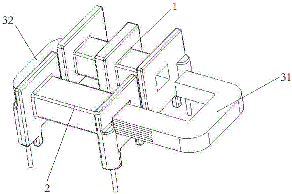
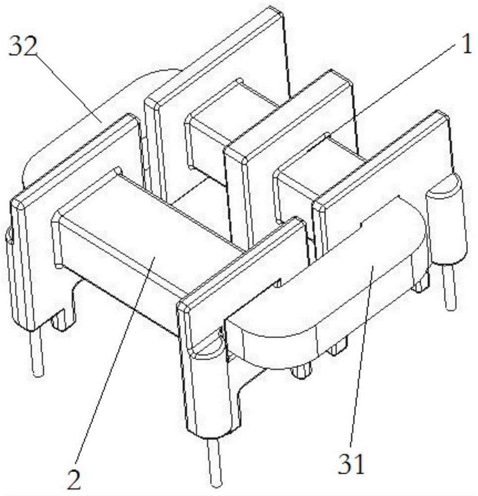
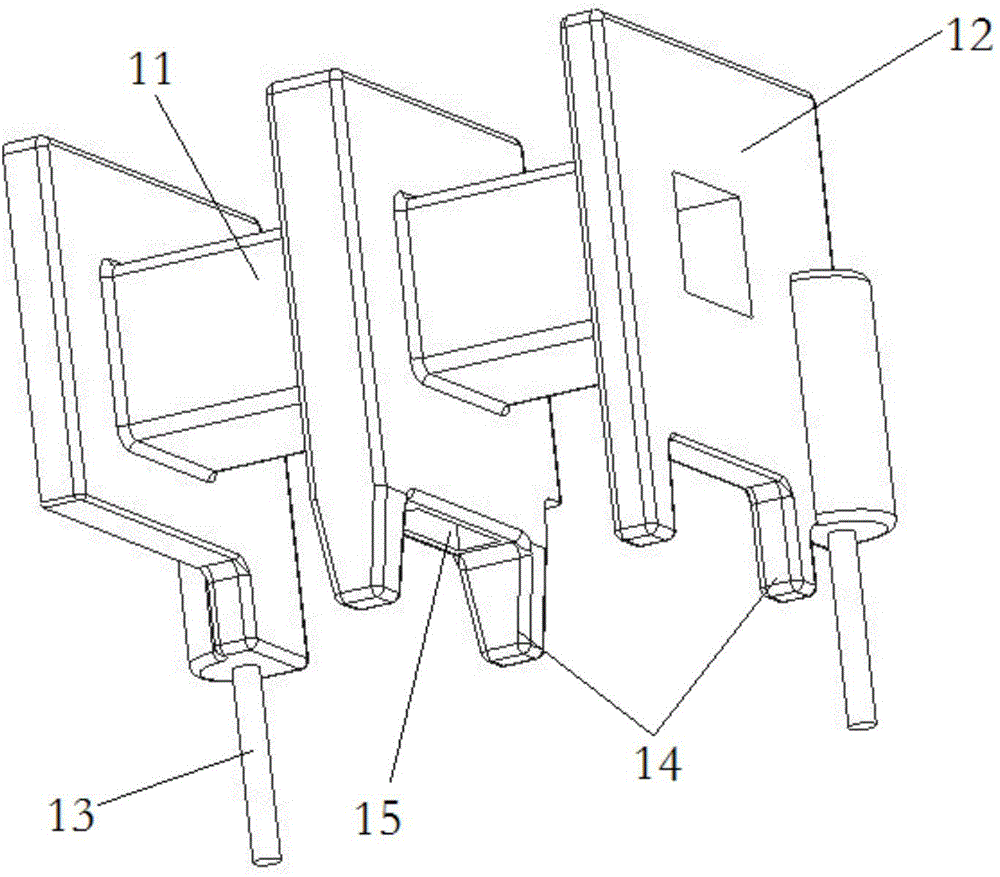
[0025] The novel framework of the present invention also includes a first framework 1 and a second framework 2; the structure of the first framework 1 is similar to the existing framework shown in Figure 1, including a straight square frame 11 for accommodating the magnetic core of the current sensor The butt joint part 34 of the square frame 11 is provided with a circle of flanges 12 at both ends and the middle of the outer circumference of the square frame 11, and a compensation coil is wound on the square frame 11 between two adjacent flanges 12. A square groove 15 is left at the bottom of the middle flange 12 for fixing the Hall element. The difference is that in the present invention, a wire slot 26 is processed at the bottom of the middle flange 12 to protect the passing enameled wire from damage. There are support legs 14 on both sides, which is co...


PUM


Abstract

The invention discloses a current sensor framework applicable to square face-to-face plugging magnetic cores. One framework is designed into an 'L' shape to enable a coil to be wound in a non face-to-face plugging part and at the air gap side, which greatly increases the application range of square face-to-face plugging magnetic cores. U-shaped grooves are machined in the two ends of a square frame of a first framework to reinforce a magnetic core, and the horizontal part of the frame body is machined into a ladder shape and is in butt joint with the upper side walls of the U-shaped grooves. Therefore, the coverage area of the frame body to the magnetic core is extended, the short-circuit risk of the coil is reduced, and the reliability, consistency and anti-jamming capability of finished induction coils are improved.

Description

technical field [0001] The invention relates to the technical field of a compensated Hall current sensor, in particular to a current sensor frame suitable for a square pair of inserted magnetic cores. Background technique [0002] As shown in Fig. 1 and Fig. 2, it is an existing current sensor with a square intersecting magnetic core, including a magnetic core and two skeletons. The first skeleton includes a straight square frame, three parallel annular flanges are evenly arranged on the outer periphery of the direction frame, and the direction frame between two adjacent flanges is used for winding compensation coils. The square frame of the second skeleton is only provided with flanges at two ends. The bottoms of the two skeletons are provided with support legs for supporting the skeletons; there is a soldering pin on both sides of the bottom, the upper ends of the soldering pins are respectively welded to one end of the two compensation coils, and the lower ends of the so...

Claims


Application Information

Patent Timeline
Patent Type & Authority Applications(China)
IPC IPC(8): G01R15/00
Inventor 王阳潘力平赵旭张乐君钟贻兵万丽丁俊鹏徐春明
Owner SHANDONG INST OF AEROSPACE ELECTRONICS TECH
Why Eureka
Try Eureka