Trigger holding device

A trigger hold and contact technology, applied in program control, instrument, computer control, etc., can solve the problem that the trigger device cannot maintain the state when encountering water, and achieve the effect of low power consumption and long standby time.

Inactive Publication Date: 2015-09-23
QINGDAO TECHNOLOGICAL UNIVERSITY
View PDF5 Cites 4 Cited by
  • Summary
  • Abstract
  • Description
  • Claims
  • Application Information

AI Technical Summary

Problems solved by technology

[0003] For this reason, the technical problem to be solved by the present invention is to overcome the state that the water trigger device in the prior art cannot maintain the state after one trigger after leaving the trigger environment, so as to propose a trigger device that can always remain after one trigger Trigger hold device in working state

Method used


Image

  • Trigger holding device
  • Trigger holding device
  • Trigger holding device

Examples


Embodiment Construction

[0035] Embodiments of the present invention will be described below with reference to the drawings. It should be noted that the terms "first", "second", "third", etc. herein, if present, are used to distinguish between similar elements and do not necessarily describe a particular order or chronological order order. It is to be understood that the terms so used are interchangeable under appropriate circumstances such that the embodiments of the subject matter described herein are, for example, capable of being performed in an order different from that described herein or in another order described herein. operate. The term "connected" is to be interpreted broadly and refers to electrically, mechanically, or otherwise connecting two or more elements or signals, either directly or indirectly through intermediate circuits and / or elements.

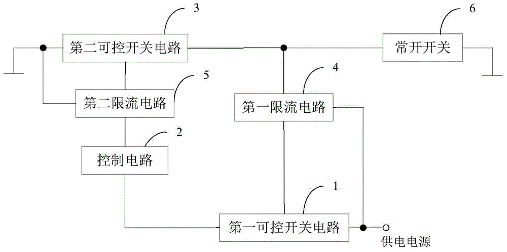
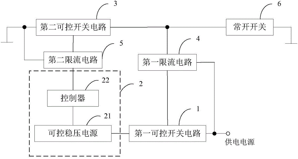
[0036] figure 1 Shows a structural block diagram of the trigger holding device of the embodiment of the present invention, as figure 1 As ...


PUM


Abstract

The present invention discloses a trigger holding device, which comprises a first controllable switch circuit, a control circuit, a second controllable switch circuit, a first current limiting circuit, a second current limiting circuit, and a normally open switch. The input end of the first controllable switch circuit is connected with a power supply. The control end of the first controllable switch circuit is connected with the output end of the first current limiting circuit. The output end of the first controllable switch circuit is connected with the input end of the control circuit. The output end of the control circuit is connected with the first input end of the second current limiting circuit. The second input end of the second current limiting circuit is grounded. The output end of the second current limiting circuit is connected with the control end of the second controllable switch circuit. The input end of the second controllable switch circuit is grounded. The output end of the second controllable switch circuit is respectively connected with the first input end of the first current limiting circuit and the first contact of the normally open switch. The second input end of the first current limiting circuit is connected with the power supply. The second contact of the normally open switch is grounded. By means of the trigger holding device, the working sate caused by the single trigger operation can be held all the time after the single trigger operation.

Description

technical field [0001] The invention relates to the field of electronic circuit design, in particular to a trigger holding device. Background technique [0002] Today, marine search and rescue terminal equipment, automatic inflation devices for inflatable life jackets, waterproof systems for electronic equipment, and safety circuits for kitchen and bathroom appliances are all equipped with trigger devices when they encounter water. It will start working when it is in the environment, and generate signals to make the marine search and rescue terminal equipment, the automatic inflation device of the inflatable life jacket, the waterproof system of the electronic equipment, and the safety circuit of the kitchen and bathroom appliances work, so as to play a protective role. However, the currently widely used water switch will stop working after leaving the trigger environment, and it cannot always maintain the state where the water switch starts to work after a trigger, that is ...

Claims


Application Information

Patent Timeline
Patent Type & Authority Applications(China)
IPC IPC(8): G05B19/042
CPCG05B19/042
Inventor 李言胜孙琳南西
Owner QINGDAO TECHNOLOGICAL UNIVERSITY
Why Eureka
Try Eureka