Behavior logic modeling method of industrial electronic system

A technology of electronic systems and modeling methods, applied in electrical digital data processing, special data processing applications, instruments, etc., can solve problems such as increased cost, inability to design result verification, simulation, etc., to reduce the workload of writing and facilitate the definition. and view the effect

Inactive Publication Date: 2015-09-23
杭州杉石科技有限公司
View PDF4 Cites 3 Cited by
  • Summary
  • Abstract
  • Description
  • Claims
  • Application Information

AI Technical Summary

Problems solved by technology

[0003] At the same time, the existing textual unstructured design results cannot be used for simulation, and traditional simulation methods mainly focus on structure, electromagnetic field finite element, control law, etc., lacking

Method used


Image

  • Behavior logic modeling method of industrial electronic system
  • Behavior logic modeling method of industrial electronic system
  • Behavior logic modeling method of industrial electronic system

Examples


Embodiment Construction

[0027] The present invention will be further described below in conjunction with the accompanying drawings and examples, and the contents of the examples are not intended to limit the protection scope of the present invention.

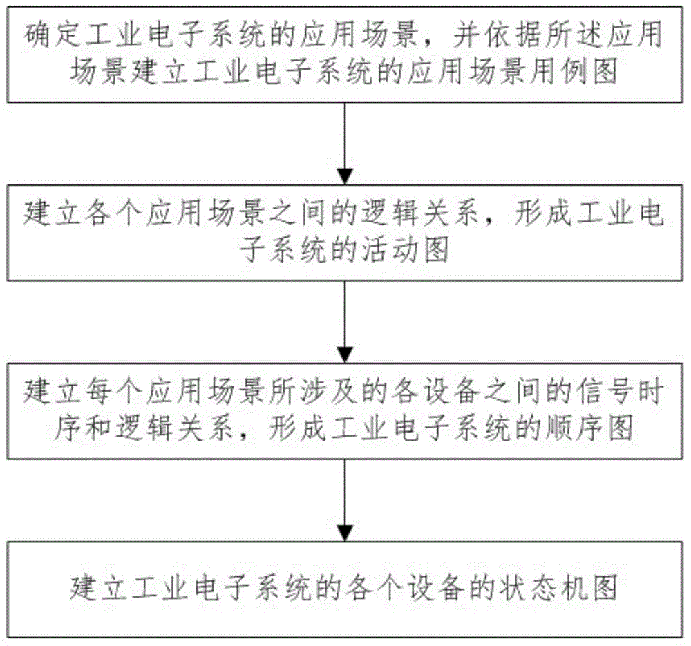
[0028] figure 1 A schematic flowchart showing the behavioral logic modeling method of the industrial electronic system of the present invention. Such as figure 1 As shown, in the behavioral logic modeling method of the industrial electronic system of the present invention, firstly, the operation process is determined according to the function of the industrial electronic system, and the application scenario of the industrial electronic system is obtained according to the operation process, and according to the application Scenario builds the application scenario use case diagram of the industrial electronic system.

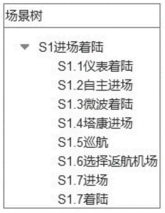
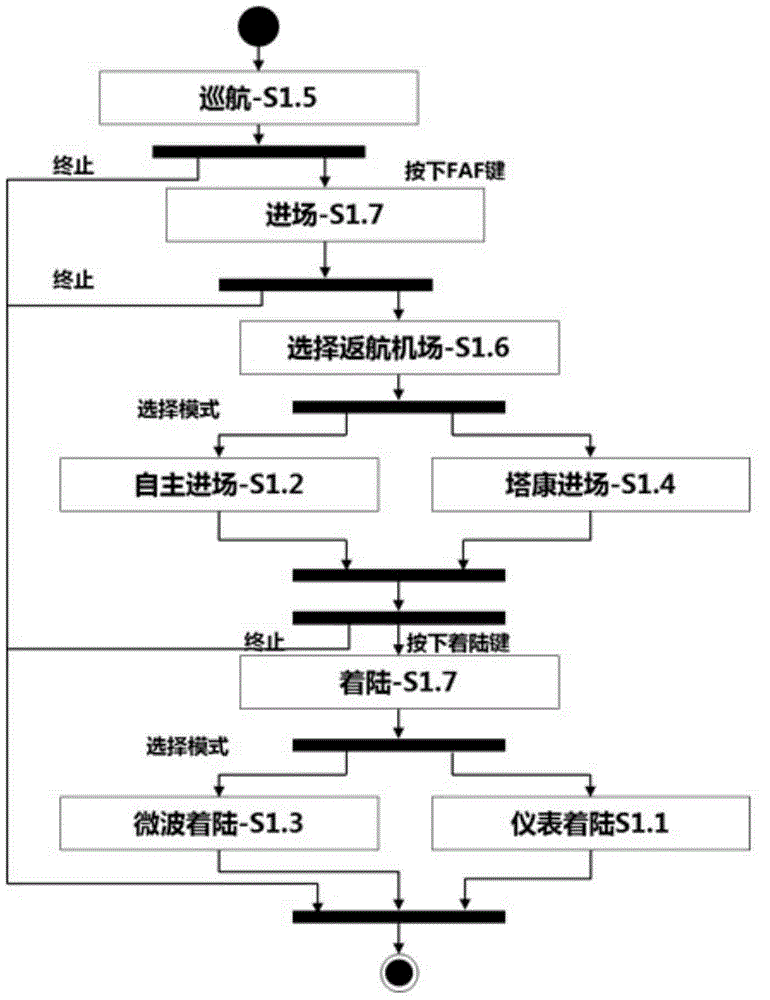
[0029] In the present invention, the use case diagram of the application scenario is a use case tree. Each use case in the use case tr...


PUM


Abstract

The invention relates to a behavior logic modeling method of an industrial electronic system. The behavior logic modeling method includes the following steps: 1, determining the running process of the industrial electronic system according to the functions of the industrial electronic system, obtaining application scenes according to the running process, and building an application scene use case diagram of the industrial electronic system according to the application scenes; 2, building logical relationships between the application scenes, and forming an activity diagram of the industrial electronic system; 3, building signal time sequences and logical relationships of devices related to each application scene, and forming a sequence diagram of the industrial electronic system; 4, building state machine diagrams of the devices of the industrial electronic system, and observing behaviors and logic of the devices in the application scenes through the state machine diagrams. According to the behavior logic modeling method, complete descriptions of the behavior logic of the industrial electronic system are achieved through the use case diagram, the activity diagram, the sequence diagram and the state machine diagrams, and a workable model can be provided for system logic simulation in the early period and functional performance affirming in the late period of research and development of the industrial electronic system.

Description

technical field [0001] The invention belongs to the technical field of industrial electronics and embedded systems, relates to the model construction of the behavioral logic of the industrial electronic system, and in particular relates to a modeling method suitable for completely describing the behavioral logic of the industrial electronic system. Background technique [0002] In the design process of the current industrial electronic system, it is necessary to define the system architecture, ICD, behavioral logic and other content. The existing design schemes are all described in the form of documents using word processing software (such as Microsoft Word). In this way, not only the workload of the text is heavy, but also the implicit design correlation between the text cannot be guaranteed, the coordination of design and change cannot be realized, and errors are difficult to find, which brings potential hidden dangers to the further development work in the later stage. I...

Claims


Application Information

Patent Timeline
IPC IPC(8): G06F17/50
Inventor 李晋章磊刘王军刘阳曹勇刘晓春杨玲杨栋王彬彬李昊泽
Owner 杭州杉石科技有限公司
Why Eureka
Try Eureka