Replacement Lens Barrel

A lens barrel and lens technology, applied to instruments, installations, camera bodies, etc., can solve the problems of complicated manufacturing processes, rising manufacturing costs, shortening lens barrels, etc., to achieve good operability and improve portability.

Active Publication Date: 2017-09-29
OM DIGITAL SOLUTIONS CORP
View PDF5 Cites 1 Cited by
  • Summary
  • Abstract
  • Description
  • Claims
  • Application Information

AI Technical Summary

Problems solved by technology

[0013] However, in the zoom lens barrel disclosed in the aforementioned Japanese Patent Laid-Open No. 10-20176, etc., it is necessary to form the fixing portion, the ring-shaped operating member, etc. in a complicated shape, and there are problems of complicating the manufacturing process and increasing the manufacturing cost.
Furthermore, no technology corresponding to the request for further shortening of the lens barrel has been disclosed.

Method used


Image

  • Replacement Lens Barrel
  • Replacement Lens Barrel
  • Replacement Lens Barrel

Examples


no. 1 Embodiment approach

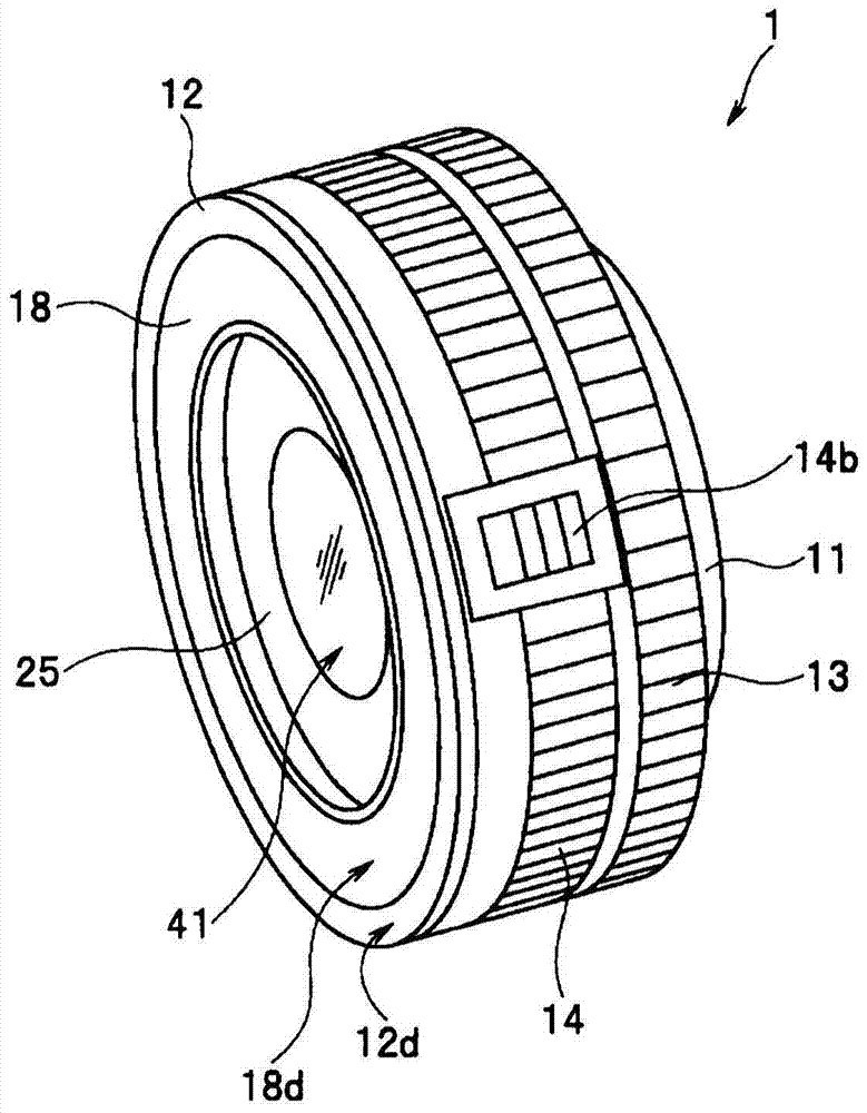
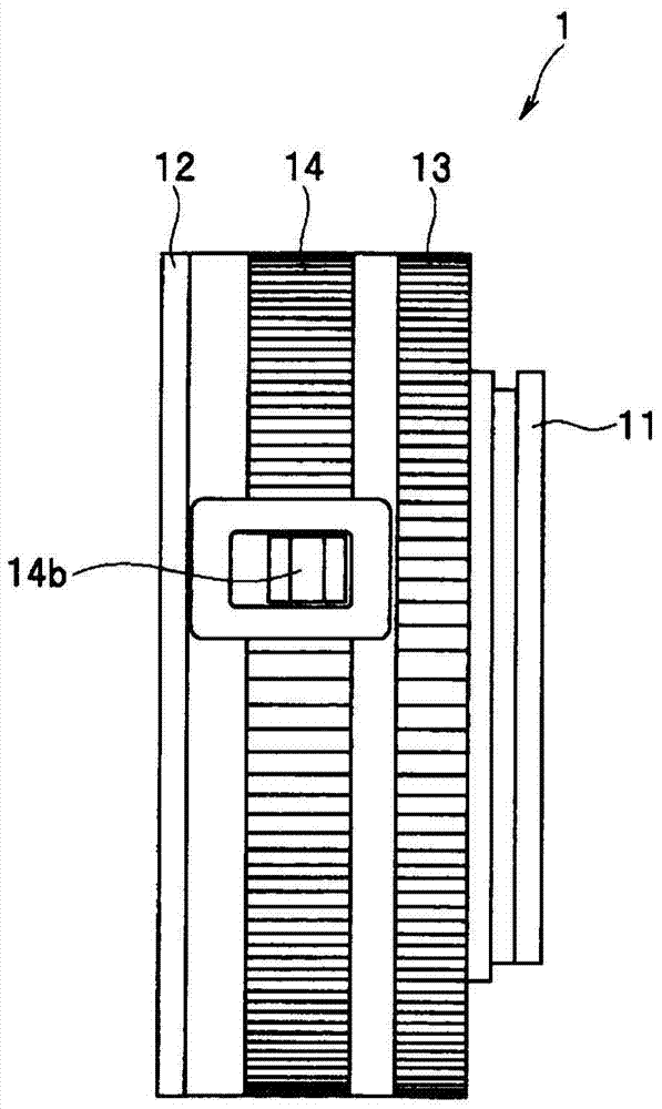
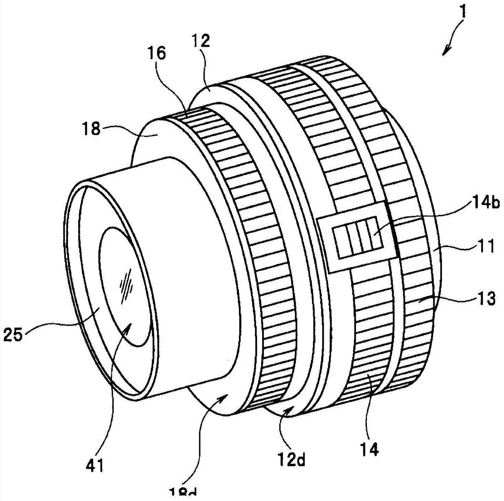
[0043] Figure 1 to Figure 10 It is a figure which shows the zoom lens barrel of 1st Embodiment of this invention. in, figure 1 It is a perspective view of the external appearance of the zoom lens barrel of the present embodiment in a contracted state. figure 2 yes figure 1 A side view of the appearance of the state of the zoom lens barrel. image 3 It is a perspective view of the appearance of the zoom lens barrel according to the present embodiment when it is in use. Figure 4 yes image 3 A side view of the appearance of the state of the zoom lens barrel. Figure 5 ~ Figure 7 It is an exploded perspective view of the zoom lens barrel of this embodiment. in, Figure 5 The structure of the front half of the zoom lens barrel of this embodiment is shown. Image 6 The structure of the rear half of the zoom lens barrel of this embodiment is shown. Figure 7 It is an exploded perspective view of main parts of the focus drive unit of the zoom lens barrel of the present em...

no. 2 Embodiment approach

[0111] The second embodiment of the present invention is exemplified when it is applied to an interchangeable zoom lens barrel used in an imaging device such as a digital camera (hereinafter simply referred to as a camera) configured as follows: The optical image is photoelectrically converted, the resulting image signal is converted into digital image data representing a still image or a moving image, and the digital data generated in this way is recorded in a recording medium, and the digital image data recorded in the recording medium can be A still image or a moving image is reproduced and displayed on the display device.

[0112]Furthermore, the interchangeable zoom lens barrel of the present embodiment is a zoom lens barrel configured to be detachable from a camera as an optical device. Furthermore, the interchangeable zoom lens barrel of the present embodiment is a shrinkable lens barrel having a contraction mechanism that shortens the state during non-shooting compared...


PUM


Abstract

The lens barrel (1) of the present invention has: a fixed frame (12), which is formed in an annular shape and has a length in the direction of the optical axis; Relatively move in the direction, be stored in the fixed frame in the non-shooting state, and be sent out to the outside of the fixed frame in the shooting state; On the frame, it has a length in the direction of the optical axis, and is rotated around the optical axis by manual operation. The first annular member is configured such that at least a part of the outer circumference of the lens barrel is exposed to the outside when the lens barrel is in a photographable state. The front end surface of the optical axis front of the ring-shaped part is more forward than the front end surface of the optical axis front of the fixed frame. The rear end surface of the rear is located in the fixed frame, and the rear end surface is closer to the rear of the optical axis than when it is in a photographable state.

Description

technical field [0001] The present invention relates to a lens barrel of a form that is shortened during non-photography compared to non-photography, and extended during non-photography. Background technique [0002] Conventionally, lens barrels used in photographing devices such as cameras are driven by a photographic optical system composed of a plurality of optical lenses, etc., and a plurality of lens barrel members for holding and moving the photographic optical system in the direction of the optical axis. Various components such as a driving component of a part of the lens barrel components among the plurality of lens barrel components, and a diaphragm mechanism are configured. [0003] Among such lens barrels, a zoom lens barrel having a photographing optical system configured to enable variable magnification so that the focal length can be continuously changed is widely used. In a zoom lens barrel, a plurality of optical lenses are used to constitute a photographing...

Claims


Application Information

Patent Timeline
Patent Type & Authority Patents(China)
IPC IPC(8): G02B7/02G02B7/04G02B7/08G03B17/14
CPCG02B7/10G02B7/102G03B17/14
Inventor 小岩井保林茂雄阴山直启外山满
Owner OM DIGITAL SOLUTIONS CORP
Why Eureka
Try Eureka