Multi-station rotary riveting machine

A riveting machine and multi-station technology, which is applied in the field of filter manufacturing, can solve the problems of low production efficiency, slow production rhythm, and high labor intensity of operators, and achieve the effects of beautiful appearance, reduced labor intensity, and improved riveting efficiency

Inactive Publication Date: 2015-09-30
蚌埠威诺过滤器有限公司
View PDF7 Cites 12 Cited by
  • Summary
  • Abstract
  • Description
  • Claims
  • Application Information

AI Technical Summary

Problems solved by technology

However, the existing riveting equipment is often operated in a single cycle. After one feeding is completed, the next feeding must wait until the riveting is completed

Method used


Image

  • Multi-station rotary riveting machine
  • Multi-station rotary riveting machine
  • Multi-station rotary riveting machine

Examples


Example Embodiment

[0019] The following examples are a further description of the content of the present invention as an explanation of the technical content of the present invention, but the essential content of the present invention is not limited to the following examples, those of ordinary skill in the art can and should know any Simple changes or replacements of the essential spirit of the invention shall fall within the scope of protection required by the present invention.

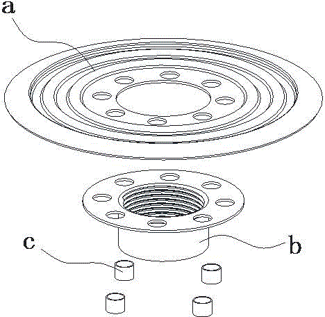
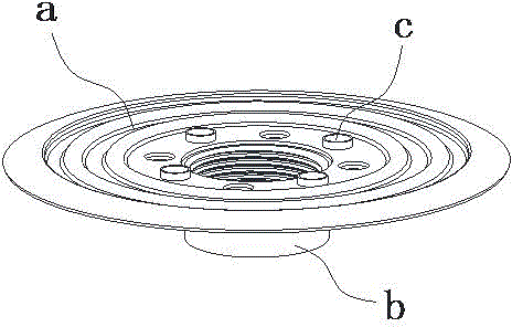
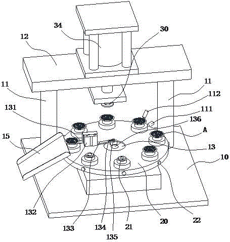
[0020] like image 3 As shown, a multi-station rotary riveting machine includes a positioning seat 21 for fixing the end cover A to be riveted, and a punch 30 arranged to reciprocate vertically above the positioning seat 21, and the positioning seat 21 is fixed On the turntable 20, the turntable 20 is rotatably arranged on the base 10, and there are at least two positioning seats 21, and each positioning seat 21 is arranged in a circular array on the turntable 20 with the rotation center of the turntable 20 as the cen...


PUM


Abstract

The invention belongs to the field of filter manufacture, and particularly relates to a multi-station rotary riveting machine. A plurality of positioning seats are arranged on a rotating plate, an operation worker can continuously perform feeding operation, and the machine is controlled through an automatic system; the positioning seats can automatically enter punching stations for riveting, and the riveting efficiency is greatly improved; meanwhile, an unloading mechanism can automatically eject out riveted end covers from the positioning seats and enables the end covers to fall into a material collecting unit, the production efficiency is greatly improved, and the labor intensity of the operator is reduced; besides, in the down pressing process of a punch, a press plate is firstly attached with one end cover and tightly presses the end cover, a mold plate and a flange on a thread tube cannot rub with each other in the riveting process, the riveting quality is good, and the rivet appearance is attractive.

Description

technical field [0001] The invention belongs to the field of filter manufacturing, and in particular relates to a multi-station rotary riveting machine. Background technique [0002] One end cover of the filter housing is provided with a threaded pipe to facilitate the connection of the engine intake system, such as figure 1 , 2 As shown, the main body of the side end cover is generally composed of a relatively thin hollow-out plate a, while the threaded pipe b is processed separately, and then the two are riveted to form a complete end cover, as shown in figure 1 As mentioned above, there is a flange b1 for riveting on the threaded pipe b, and the operator first pre-loads the rivet c into the riveting hole on the flange b1 and the template a, and then puts the entire end cover on the stamping equipment Implement riveting. However, the existing riveting equipment is often operated in a single cycle. After one feeding is completed, the next feeding must wait until the rive...

Claims


Application Information

Patent Timeline
IPC IPC(8): B21J15/14B21J15/36B21J15/38B21J15/30
CPCB21J15/14B21J15/30B21J15/36B21J15/38
Inventor 牛立彬
Owner 蚌埠威诺过滤器有限公司
Why Eureka
Try Eureka