Pneumatic tire

一种充气轮胎、轮胎的技术,应用在充气轮胎、轮胎零部件、轮胎胎面/胎面花纹等方向,能够解决胎肩横纹沟排水性能降低、干燥路面转弯性能变差、胎面部刚性降低等问题,达到提高排水性能、提高转弯性能、提高排水性能与外观性能的效果

Active Publication Date: 2015-09-30
SUMITOMO RUBBER IND LTD
View PDF6 Cites 10 Cited by
  • Summary
  • Abstract
  • Description
  • Claims
  • Application Information

AI Technical Summary

Problems solved by technology

[0004] However, in the pneumatic tire described in Patent Document 1, the depth near the inner end of the shoulder lug groove is large, so the rigidity of the tread portion tends to decrease, and there is a possibility that the cornering performance on a dry road surface may deteriorate.
In addition, there is a concern that the drainage performance of the shoulder lug grooves may be reduced due to the raised bottom.

Method used


Image

  • Pneumatic tire
  • Pneumatic tire
  • Pneumatic tire

Examples


Embodiment

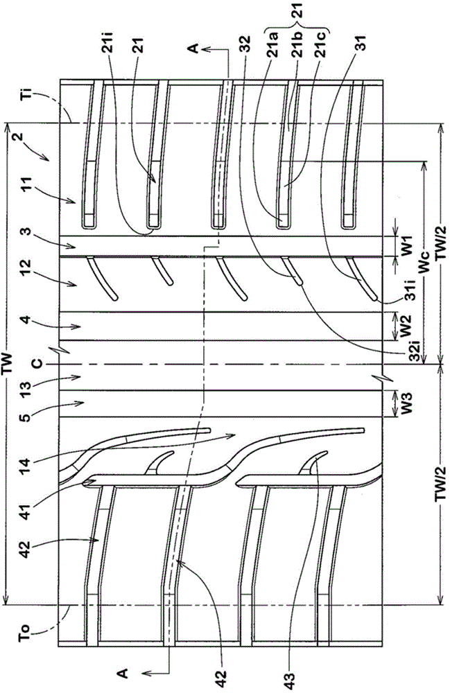
[0054] Prototypes based on the specifications in Table 1 have figure 1 The tread pattern size is 245 / 40R18 pneumatic tires, and the turning performance, drainage performance and appearance performance in the middle of wear are tested. The test method is as follows.

[0055]

[0056] For a test tire mounted on a rim of 18×8.5J, the maximum cornering force was measured using a flat belt testing machine under the conditions of an internal pressure of 230kPa and a load of 6.86kN. The result is shown by the index which set Example 1 to 100. A larger value indicates better cornering performance.

[0057]

[0058] A vehicle mounted with the above-mentioned pneumatic tire was run on a wet road surface having a road surface μ of 0.3 and a water depth of 1.4 mm, and the ease of turning was evaluated by the driver's senses. The results are shown by setting Example 1 as a score of 100, and the larger the numerical value, the better the drainage performance.

[0059]

[0060] The...


PUM


Abstract

A pneumatic tire comprises a tread portion provided with a shoulder main groove and shoulder blind grooves. The shoulder blind grooves extend axially inwardly from one of the tread edges and each having an axially inner blind end. The shoulder main groove extends circumferentially of the tire on the axially inside of the axially inner blind ends of the shoulder blind grooves. Each shoulder blind groove is provided with an axially inner shallow part, an axially outer deep part, and a sloped part therebetween having a depth gradually increasing from the shallow part towards the deep part, and having an axially outer end positioned at a distance from the tire equator which is 42.5 % to 45 % of the tread width.

Description

technical field [0001] The present invention relates to a pneumatic tire capable of improving cornering performance on a dry road and drainage performance on a wet road. Background technique [0002] A pneumatic tire is known which has, in a tread portion: a shoulder main groove extending continuously in the tire circumferential direction on the side closest to the tread end; The shoulder main grooves are connected to form shoulder lug grooves at the inner end of the terminal. For example, Patent Document 1 discloses a pneumatic tire having a shoulder lug groove having a raised bottom having a raised groove bottom formed near an end portion of a belt layer. [0003] Patent Document 1: WO2012 / 026546 Publication [0004] However, in the pneumatic tire described in Patent Document 1, the depth near the inner end of the shoulder lug groove is large, so the rigidity of the tread portion tends to decrease, and there is a possibility that the cornering performance on a dry road s...

Claims


Application Information

Patent Timeline
Patent Type & Authority Applications(China)
IPC IPC(8): B60C11/03B60C11/13
CPCB60C11/03B60C2011/0369B60C2011/0381B60C11/04B60C2011/0388B60C2011/0374B60C11/0304B60C5/00B60C11/01B60C11/1263B60C11/13
Inventor 上郡纯
Owner SUMITOMO RUBBER IND LTD
Why Eureka
Try Eureka