Cross beam transport material rack

A material rack and beam technology, which is applied in the field of beam transport material racks, can solve problems such as the tight space in the production workshop, and achieve the effects of reducing logistics costs, saving space, and saving production space

Inactive Publication Date: 2015-09-30
YANFENG WEISHITONG LIUZHOU AUTOMOBILE ACCESSORIES
View PDF7 Cites 2 Cited by
  • Summary
  • Abstract
  • Description
  • Claims
  • Application Information

AI Technical Summary

Problems solved by technology

The variety of products is increasing day by day. If one type of transport rack can only store one product according to the current situation, then in the flexible production workshop, it is necessary to equip a variety of transport racks to store different products. The increase in the types of transport racks will cause production Tensions on the workshop floor
How to solve the production requirements of the transportation rack to adapt to the assembly and manufacture of various products, and reduce the problem of the tight space of the production workshop caused by the transport rack has become a major issue

Method used


Image

  • Cross beam transport material rack
  • Cross beam transport material rack
  • Cross beam transport material rack

Examples


Embodiment 1

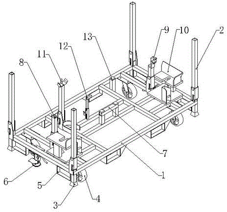
[0027] Utilize the first positioning mechanism to position and store the product. The positioning block I11 and the positioning block II12 of the second positioning mechanism are also connected with the bottom frame 1 by the sliding groove structure as the movable column 2. After the positioning block I11 and the positioning block II12 are respectively pulled upward, the protrusions of the positioning block I11 and the positioning block II12 The block 19 exits from the V-shaped groove 16, and the positioning block I11 and the positioning block II12 are placed sideways on the open side of the support 14 on the chassis 1, so that the positioning block I11 and the positioning block II12 do not affect the first positioning mechanism on the product. Positioning storage, positioning block III13 does not affect product storage due to its short length.

[0028] Use the positioning plate I7, the positioning plate II8, the positioning plate III9 and the positioning plate IV10 of the fir...

Embodiment 2

[0030] Utilize the second positioning mechanism to locate and store additional products. The positioning plate II8 and the positioning plate III9 of the first positioning mechanism are also connected with the bottom frame 1 by the sliding groove structure as the movable column 2. After the positioning plate II8 and the positioning plate III9 are respectively pulled upward, the protrusions of the positioning plate II8 and the positioning plate III9 will Block 19 exits from the V-shaped groove 16, and the positioning plate II8 and positioning plate III9 are placed sideways on the open side of the support 14 on the chassis 1, so that positioning plate II8 and positioning plate III9 do not affect the first positioning mechanism on the product. Positioning storage, positioning plate I7 ​​and positioning plate IV10 do not affect the storage of products due to their short length.

[0031] Utilize the positioning block I11, the positioning block II12 and the positioning block III13 of...

Embodiment 3

[0033] The upright and flat laying of movable column 2.

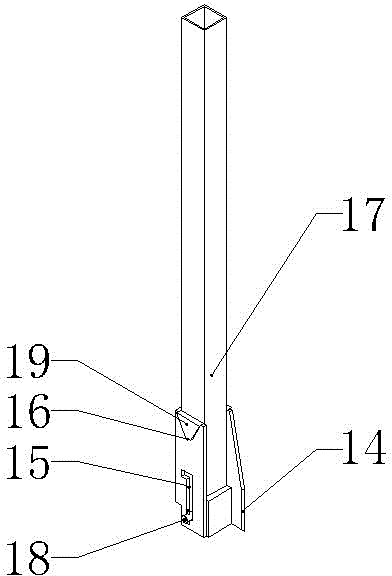
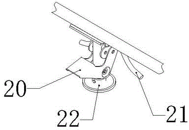
[0034] When the transport material rack needs to store products, the movable column 2 is in an upright state, that is, the protrusion 19 of the movable column 2 is put into the V-shaped groove 16, and the V-shaped groove 16 blocks the protrusion 19, thereby fixing the Upright bar 17, upright bar 17 is upright state, and promptly movable column 2 is upright state. At this moment, the bottom of the support foot 3 can cooperate with the movable column 2, and the bottom of the support foot 3 of one transport material rack is stacked on the top of the vertical bar 17 of another transport material rack. put, effectively saving space.

[0035] When the transport material rack does not need to store products, lift up the vertical rod 17, the block 18 slides upward in the chute 15, and the protrusion 19 moves upward to break away from the V-shaped groove 16. At this time, the vertical rod 17 can be placed on the open side of th...


PUM


Abstract

The invention discloses a cross beam transport material rack. The cross beam transport material rack is characterized in that (1) through the connection of sliding groove structures and movable stand columns, the movable stand columns can be erected and also can be flatly laid on an under carriage; when products are stored on the transport material rack, the movable stand columns are erected, and a plurality of transport material racks can be stacked through the matching of supporting legs and the movable stand columns; when no product is stored on the transport material rack, the movable stand columns are flatly laid on the under carriage, and a plurality of transport material racks are stacked through the matching of the supporting legs and supports of the moving groove structures, so that space is effectively saved in the stacking mode; (2) the transport material rack can be used for positioning two sorts of products through a first positioning mechanism and a second positioning mechanism, namely, the transport material rack can be used for storing two sorts of products, various sorts of products can be stored through the transport material rack, the variety of the transport material racks is effectively reduced, production space is saved, the turnover rate of the transport material rack is increased, and logistics cost is lowered; (3) trundles, forklift grooves, ground brakes and the like are mounted to be used for moving fixed parts, hence, the transport material rack can be moved and fixed conveniently, and the transport material rack is suitable for various transport modes.

Description

technical field [0001] The invention relates to the field of automobile manufacturing, in particular to a beam transport rack. Background technique [0002] In the field of automobile beam manufacturing, it is often necessary to use transport racks for product storage and circulation. Existing transport racks are often designed as transport racks for specific products, that is, the transport racks only have a positioning mechanism for a designated product to meet the storage of the product, and have a single function. At present, the factory advocates flexible production, that is, a workshop and a production line often involve the assembly and manufacture of different products. The variety of products is increasing day by day. If one type of transport rack can only store one product at present, then in the flexible production workshop, a variety of transport racks need to be equipped to store different products. The increase in the types of transport racks will cause produc...

Claims


Application Information

Patent Timeline
Patent Type & Authority Applications(China)
IPC IPC(8): B65G7/02
Inventor 沈王彪余长旺姜莉莉蓝志伟韦松
Owner YANFENG WEISHITONG LIUZHOU AUTOMOBILE ACCESSORIES
Why Eureka
Try Eureka