Flushing toilet

A toilet and flushing technology, which is applied in flushing toilets, water supply devices, buildings, etc., can solve the problems of increased flushing water volume, inability to form the mainstream of the inlet of the drainage elbow pipe, and unfixed position, so as to improve drainage performance effect

Active Publication Date: 2015-09-30
TOTO LTD
View PDF5 Cites 10 Cited by
  • Summary
  • Abstract
  • Description
  • Claims
  • Application Information

AI Technical Summary

Problems solved by technology

[0004] However, in the flush toilet described in Patent Document 1, in order to improve the cleaning performance of the basin surface, for example, the jet water spout is removed, and only the swirling flow of the flush water spouted from the inner edge spout is intended. When washing the surface of the basin, the volume of the washing water spouted from the spout on the inner edge increases, so that the water potential of the swirling washing water increases, and the main flow toward the inlet of the drain elbow cannot be formed.
Specifically, the water potential of the washing water swirling along the inner peripheral surface of the inner edge portion becomes stronger, and the position where the water flows down toward the bowl surface of the bowl portion is not fixed, so that a bundled main flow toward the inlet of the drain trap cannot be formed.
Therefore, when it is intended to wash the basin surface of the basin with the washing water spouted from the inner edge water spout, the problem of a decrease in the discharge performance of the dirt occurs.

Method used


Image

  • Flushing toilet
  • Flushing toilet
  • Flushing toilet

Examples


Embodiment Construction

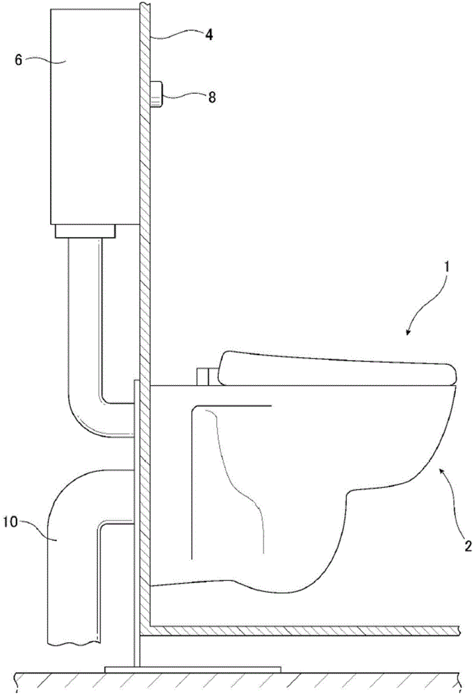
[0041] Next, a flush toilet according to a first embodiment of the present invention will be described with reference to the drawings. First, use figure 1 The installation state of the flush toilet according to this embodiment will be described. figure 1 It is a schematic diagram showing the state where the flush toilet according to the first embodiment of the present invention is installed on a wall surface. Such as figure 1 As shown, reference numeral 1 denotes the flush toilet 1 of the present embodiment, which is a flush flush type that uses the drop generated by the rise of the water level in the drain trap pipeline to discharge waste, which will be described later. Toilet (flush toilet). In addition, in this embodiment, the flush toilet may also be other types of toilets such as a siphon flush toilet.

[0042] The flush toilet 1 includes a toilet body 2 attached to a wall 4 . A water storage tank 6 for storing flush water is attached to the back side of the wall 4 , a...


PUM


Abstract

The invention provides a flushing toilet capable of truly forming a beamed main stream facing an inlet of a drain elbow portion, thus improving sewage discharge performance; specifically, the flushing toilet (1) comprises the following elements: a basin portion (12) having basin sewage bearing surface (16) and an inner edge (18) positioned in the upper edge and having an inner periphery; a drain elbow pipe (14) discharging the sewage; an inner edge water sprayer portion (28) spraying cleaning water from the inner edge water sprayer along the inner periphery of the inner edge, thus forming a convolution flow. The inner edge portion allows the inner periphery to expose to an inner space of the basin portion, thus forming a suspension shape; the inner periphery (30) comprises the bottom face (30a), a side face (30b) extending from the outer end of the bottom edge to an upper portion, and an upper surface (30c) extending from the top of the side face to the inner space; guide portions (40, 50) are formed in the basin portion and used for guiding the cleaning water, sprayed from the inner sprayer portion, to the top of the inner edge portion, to the water can fall to a set position of the basin portion.

Description

technical field [0001] The present invention relates to a flush toilet, and more particularly to a flush toilet such as a flush toilet that cleans a toilet body and discharges waste with flush water supplied from a water supply source. Background technique [0002] There is known a flush toilet in which the inner edge of the toilet is formed in an overhanging shape protruding upward toward the inner space of the bowl in order to improve cleaning performance, and flush water is spouted horizontally from the inner edge spout, so that The water swirling along the inner peripheral surface of the rim part flows down to the bowl surface for cleaning (Patent Document 1). In this flush toilet, in order to improve the waste discharge performance, the width of the table portion for forming the main flow from the front toward the elbow is gradually narrowed toward the front end portion of the bowl portion. In addition, in addition to the inner edge water discharge port provided in the...

Claims


Application Information

Patent Timeline
Patent Type & Authority Applications(China)
IPC IPC(8): E03D11/08E03D11/06
Inventor 冈田圭介大久保麻友浦田伸一木村知之古谷洋一永富洋文
Owner TOTO LTD
Why Eureka
Try Eureka