Multifunctional control valve

A multi-functional control valve and valve body technology, applied in the direction of control valve, functional valve type, multi-way valve, etc., can solve the problems of unstable water temperature at the outlet of the mixing valve, reducing the service life of the water storage container, and hot water outflow, etc. Achieve the effect of avoiding user's property loss, simple structure and reducing work pressure

Inactive Publication Date: 2015-09-30
山东龙普太阳能股份有限公司
View PDF6 Cites 7 Cited by
  • Summary
  • Abstract
  • Description
  • Claims
  • Application Information

AI Technical Summary

Problems solved by technology

The advantages are: the pressure of the cold water inlet and the hot water inlet of the mixing valve are equal, the water temperature after mixing is constant, and is basically not affected by the change of the water source pressure. The disadvantage is that the water storage container of the water heater works under high pressure for a long time, which will greatly reduce the water storage. Service life of the container
[0004] The water storage water heater with an open water outlet structure, the hot water outlet of the water storage container (liner) is connected to the atmosphere, the advantage is: the water storage container of the water heater is in a pressure-free state, and the inner tank has a long service life; the disadvantage is: the outlet of the mixing valve The water temperature is unstable with the change of water source pressure. At the same time, when the mixing valve is closed, a small stream of hot water will flow out, which is easy to scald people. At present, only a few manufacturers use water heaters with an open water storage structure.

Method used


Image

  • Multifunctional control valve
  • Multifunctional control valve

Examples


Embodiment Construction

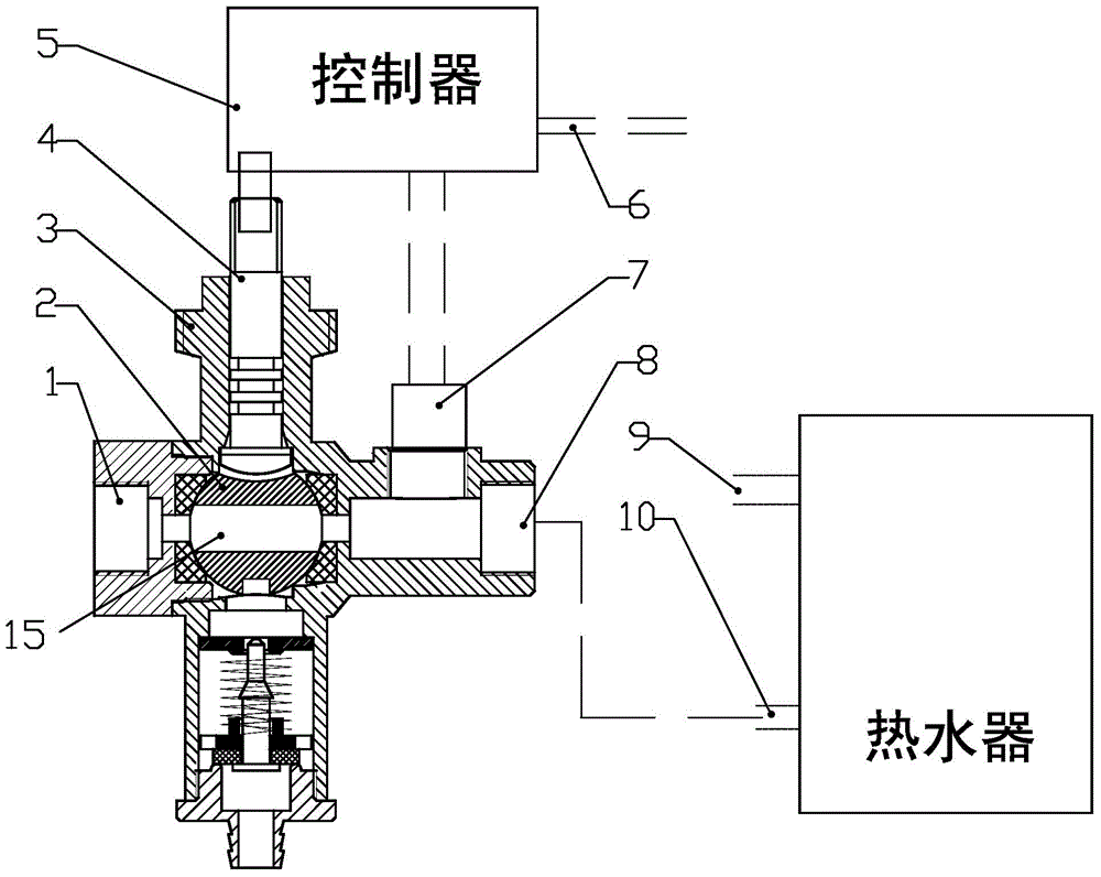
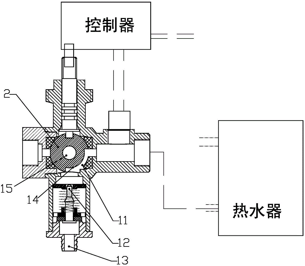
[0017] The following is attached Figure 1-2 The features and principles of the present invention are described in detail, and the examples given are only used to explain the present invention, not to limit the protection scope of the present invention.

[0018] Such as figure 1 As shown, the multifunctional control valve includes a valve body 3, and a cavity for installing a valve ball 2 is provided in the valve body. The valve ball 2 is installed in the cavity, and the valve ball 2 can be placed in the cavity under the action of external force. turn. A valve water inlet 1 is arranged on the left side of the valve body, and the valve water inlet 1 communicates with the tap water pipe. The right side of the valve body is provided with a valve water outlet 8, and the valve water outlet 8 communicates with the cold water inlet of the water heater. The valve water inlet 1 and the valve water outlet 8 are at the same horizontal position, and the valve ball 2 is provided with a ...


PUM


Abstract

A multifunctional control valve comprises a valve body, a valve ball, a rotating shaft and a pressure sensor. A valve water inlet and a valve water outlet are formed in the valve body and can be communicated with a horizontal channel of the valve ball, and therefore cold water is injected to a water heater when water pressure is low. A notch is further formed in the valve ball, so that a pressure relief channel is formed between the valve ball and the valve body, and the pressure relief channel is communicated with the valve water outlet and an overflow opening. The valve ball can be driven by the rotating shaft to rotate forwards by 90 degrees and rotate reversely by 90 degrees, so that conversion of water flowing and stopping is achieved, and pressure of the water heater is adjusted. The pressure sensor is arranged at the valve water outlet and connected with a controller through a wire, and the controller controls a motor to act according to pressure values detected by the pressure sensor. Automatic closing can be achieved when the detected pressure value exceeds a set working pressure value, automatic pressure relief can be carried out when the pressure value exceeds a set pressure relief value, the water heater is maintained to work at a low water pressure state, the service life of the water heater can be prolonged, and stability of water outlet temperature is guaranteed.

Description

technical field [0001] The invention relates to the technical field of fluid control valves, in particular to a multifunctional control valve for keeping a water storage water heater working in a low water pressure state and having an overpressure protection function. Background technique [0002] At present, there are two common structural types of domestic water storage water heaters, one is a closed structure, and the other is an open water outlet structure. [0003] A storage water heater with a closed structure. The advantages are: the pressure of the cold water inlet and the hot water inlet of the mixing valve are equal, the water temperature after mixing is constant, and is basically not affected by the change of the water source pressure. The disadvantage is that the water storage container of the water heater works under high pressure for a long time, which will greatly reduce the water storage. The service life of the container. [0004] The water storage water h...

Claims


Application Information

Patent Timeline
Patent Type & Authority Applications(China)
IPC IPC(8): F16K11/087F16K15/18
CPCF16K11/087F16K15/1848
Inventor 于彬芝
Owner 山东龙普太阳能股份有限公司
Why Eureka
Try Eureka