
Gradient amplifier applying coupled inductors to output filter

A technology of gradient amplifiers and coupled inductors, which is applied in the directions of instruments, electric variable adjustment, and magnetic resonance measurement, can solve the problems of unsatisfactory low ripple and fast response, high switching frequency, and unsatisfactory, and achieve small size and low Effect of hardware cost, design simplification

Inactive Publication Date: 2015-09-30
LIAONING KAMPO MEDICAL SYST
View PDF3 Cites 13 Cited by
  • Summary
  • Abstract
  • Description
  • Claims
  • Application Information

AI Technical Summary

Problems solved by technology

The gradient amplifiers commonly used at the present stage, in the design of the output inductor filter part, the working voltage is low, most of them directly use high saturation current and low AL value magnetic core winding inductors for filtering. This design requires high switching frequency. Or multi-channel relatively low-frequency switching circuits are phase-shifted to achieve high-frequency effects, otherwise the requirements for low ripple and fast response cannot be met; in designs with high operating voltages, large inductors are generally connected in parallel or multiple small inductors are connected in series, or a series-parallel combination
The gradient amplifier designed with the above design method has large volume, complex structure and high cost, but the key performances such as fast response, low ripple and high fidelity are not satisfactory

Method used


Image

  • Gradient amplifier applying coupled inductors to output filter
  • Gradient amplifier applying coupled inductors to output filter
  • Gradient amplifier applying coupled inductors to output filter

Examples


Embodiment Construction

[0030] The present invention will be further described in detail below in conjunction with the accompanying drawings and embodiments.

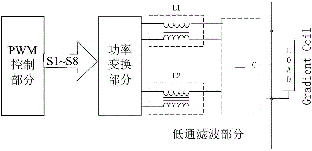
[0031] Gradient amplifier of the present invention such as figure 1 As shown, it consists of PWM control part, power conversion part, coupled inductor part and low-pass filter capacitor part.

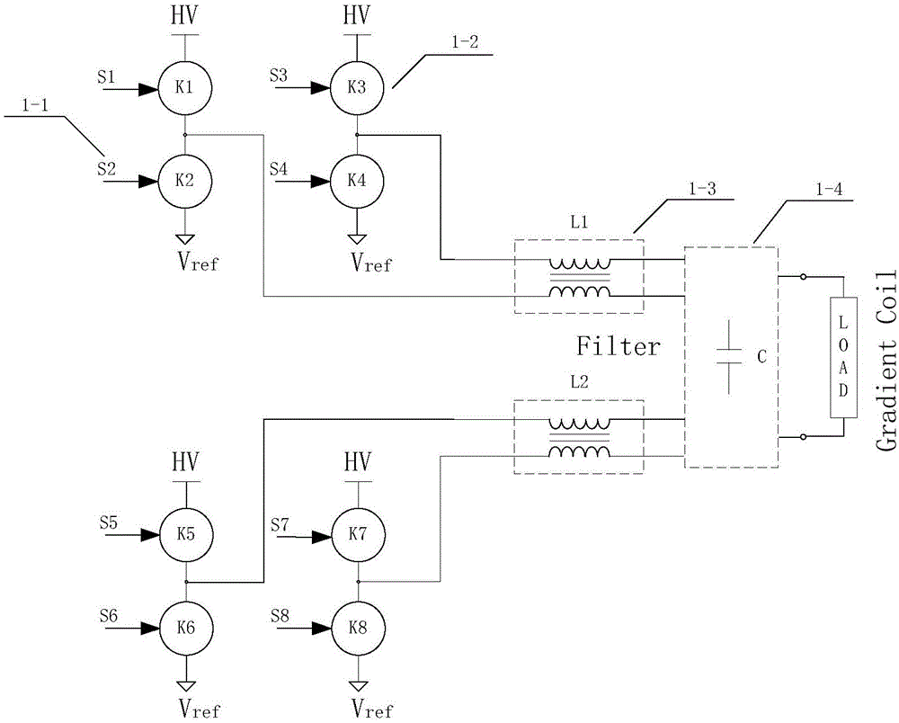
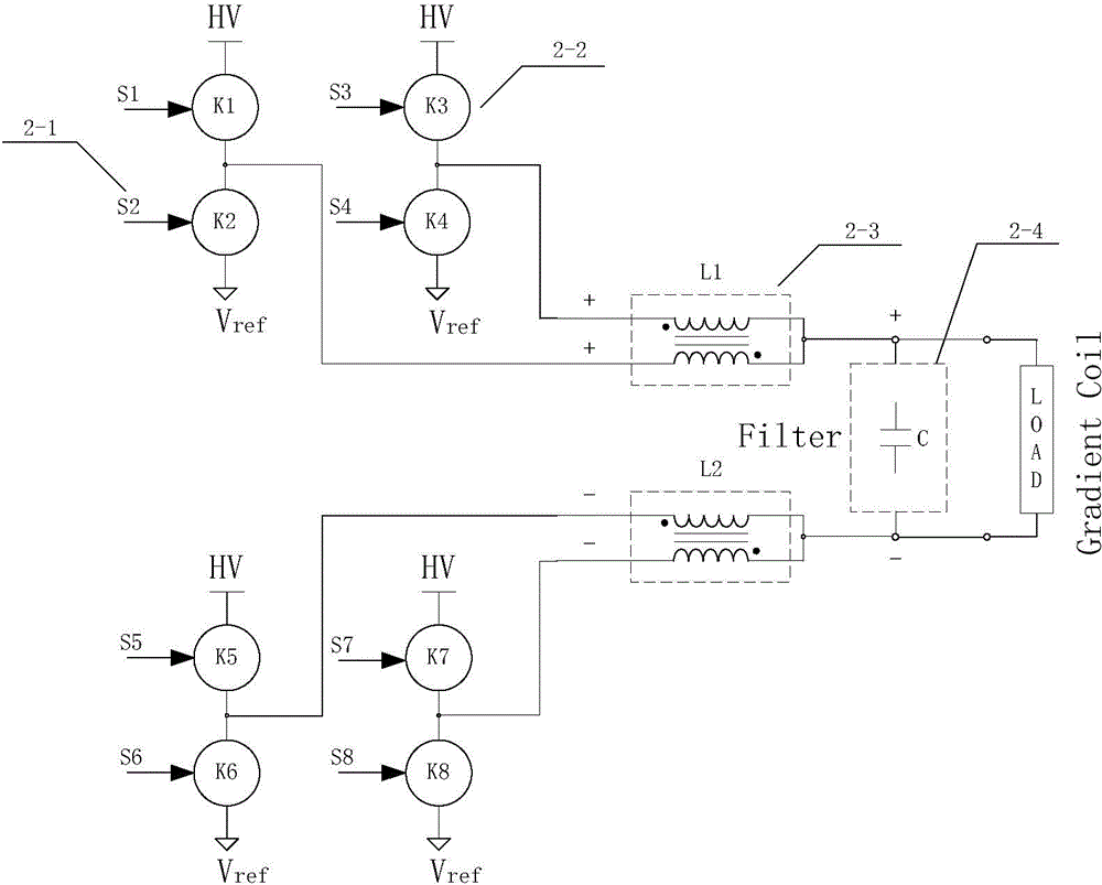
[0032] The PWM control part is used to process the input gradient control signal and the feedback signal from the sensor, and output the PWM control signal S1~S8, and according to the control logic, the PWM control signal is output to drive each power switching device K1~K8 of the power conversion part ;

[0033] The power conversion part is used to receive the PWM control signal, drive the power switching devices K1~K8 to turn on and off, and convert the high-voltage voltage into a high-voltage pulse; output the high-voltage pulse to the coupled inductance part;

[0034] The coupled inductance part is used to couple into different inductances accordi...


PUM


Abstract

The invention provides a gradient amplifier applying coupled inductors to output filter, so as to meet requirements of an imaging system with low output ripple current and quick output response. The gradient amplifier by applying the coupled inductors to output filter is composed of a PWM control part, a power conversion part and a low pass filter part. According to the gradient amplifier of the invention, design of the coupled inductors is optimized, different control logics of the PWM control signals drive power conversion and output, a low pass filter capacitor part is combined, and requirements of the imaging system with low output ripple current and quick gradient current output response can be met. According to the gradient amplifier of the invention, the coupled inductors are applied to output filter, design of the high-voltage large-current amplifier can be simplified and optimized, effectiveness and performance of the gradient system are enhanced, the hardware cost is reduced, and the cost performance of the gradient system is greatly improved.

Description

technical field [0001] The invention relates to the field of gradient amplifiers, in particular to a gradient amplifier using coupled inductance output filtering, which is used to generate and control pulse currents in gradient coils in a magnetic resonance imaging system. Background technique [0002] The gradient system refers to all circuit units related to the gradient magnetic field. Its function is to provide the system with a rapidly switchable gradient field with linearity and precision that meets the requirements, so as to dynamically modify the main magnetic field and realize the spatial positioning of imaging voxels. In the gradient system, the control signal generated by the gradient waveform generator is used as the input of the gradient amplifier, and the current output of the gradient amplifier drives three sets of gradient coils to generate a gradient field in the imaging space, giving the spatial coordinates of the imaging site, so that each pixel in the ima...

Claims


Application Information

Patent Timeline
Patent Type & Authority Applications(China)
IPC IPC(8): G01R33/38G05F1/10G05F1/66
Inventor 孔祥林吴继锋施金泉卢广
Owner LIAONING KAMPO MEDICAL SYST
Learn More