A fluorescent lamp drive circuit

A drive circuit and fluorescent lamp technology, applied in the electronic field, can solve the problems of low-frequency flicker and low-frequency noise, easy to be affected by the outside world, easy to shorten the life of fluorescent lamps, etc., and achieve the effect of extending life

Active Publication Date: 2019-04-16
OCEANKING DONGGUAN LIGHTING TECH +2
View PDF6 Cites 0 Cited by
  • Summary
  • Abstract
  • Description
  • Claims
  • Application Information

AI Technical Summary

Problems solved by technology

Fluorescent lamps are high-efficiency lighting sources. Under the existing technology, fluorescent lamps generally use inductive or electronic ballasts. At present, due to the large power consumption of inductive ballasts and the disadvantages of low-frequency flicker and low-frequency noise, electronic ballasts are replaced by electronic ballasts. Ballasts are gradually replacing
At present, electronic ballasts use self-oscillating boosting method to drive and adjust fluorescent lamps. Although the circuit structure of the driving method is simple, it is easy to shorten the life of fluorescent lamps due to the limitation of many factors such as no power, and is easily affected by the outside world. , and even prone to security risks
In addition, if the filament of the fluorescent lamp is damaged, the circuit driving the fluorescent lamp will continue to work because the fluorescent lamp is not detected, and the output terminal in the driving circuit will continue to generate high voltage, and there is a danger of high voltage electric shock

Method used


Image

  • A fluorescent lamp drive circuit
  • A fluorescent lamp drive circuit
  • A fluorescent lamp drive circuit

Examples


Embodiment Construction

[0063] The following will clearly and completely describe the technical solutions in the embodiments of the present invention with reference to the accompanying drawings in the embodiments of the present invention. Obviously, the described embodiments are part of the embodiments of the present invention, but not all of them. Based on the embodiments of the present invention, all other embodiments obtained by persons of ordinary skill in the art without creative efforts fall within the protection scope of the present invention.

[0064] By adopting the embodiment of the present invention, it is possible to drive the fluorescent lamp to work and adjust the light of the fluorescent lamp under the occasion of low voltage.

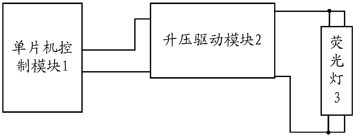
[0065] see figure 1 , figure 1 It is a schematic diagram of the module structure composition of an embodiment of the fluorescent lamp drive circuit of the present invention. A fluorescent lamp drive circuit provided by an embodiment of the present invention i...


PUM


Abstract

An embodiment of the invention provides a fluorescent lamp drive circuit including single-chip microprocessor control module, a boost drive module and a fluorescent lamp. The single-chip microprocessor control module performs main control over the fluorescent lamp drive circuit. The boost drive module is connected to the single-chip microprocessor control module, is controlled by the single-chip microprocessor and is used for generating high frequency voltage for driving the fluorescent lamp to work. By adopting the fluorescent lamp drive circuit, the fluorescent lamp can be driven to work in a low-voltage occasion and light dimming can be performed. Besides, working condition of the fluorescent lamp can be detected in real time and the service lifetime of the fluorescent lamp can be prolonged.

Description

technical field [0001] The invention relates to the field of electronic technology, in particular to a fluorescent lamp driving circuit. Background technique [0002] With the development of electronic science and technology, fluorescent lamps have become one of the lighting sources widely used in daily life and even commercial activities. Fluorescent lamps are high-efficiency lighting sources. Under the existing technology, fluorescent lamps generally use inductive or electronic ballasts. At present, due to the large power consumption of inductive ballasts and the disadvantages of low-frequency flicker and low-frequency noise, electronic ballasts are replaced by electronic ballasts. Ballasts are gradually replaced. At present, electronic ballasts use self-oscillating boosting method to drive and adjust fluorescent lamps. Although the circuit structure of the driving method is simple, it is easy to shorten the life of fluorescent lamps due to the limitation of many factors ...

Claims


Application Information

Patent Timeline
Patent Type & Authority Patents(China)
IPC IPC(8): H05B41/36
Inventor 周明杰黄晓东
Owner OCEANKING DONGGUAN LIGHTING TECH
Why Eureka
Try Eureka