A multi-functional integrated lighting and pest control system

A multi-functional, insect-killing technology, applied in lighting devices, lighting devices, lighting auxiliary devices, etc., can solve problems such as affecting insecticidal effect, pest escape, and poor working environment of insecticidal lamps, and improve the probability of catching mosquitoes. Improve the time of rotating work and improve the effect of after-sales service response

Active Publication Date: 2022-03-11
CHONGQING UNIV OF ARTS & SCI +1
View PDF0 Cites 0 Cited by
  • Summary
  • Abstract
  • Description
  • Claims
  • Application Information

AI Technical Summary

Problems solved by technology

[0003] At present, the high-voltage power grid of the equipment cannot be cleaned automatically, and it is easy to be stained with pests and rust, and is easy to be damaged, which seriously affects the insecticidal effect
In addition, the existing insecticidal lamps need to be connected to the mains, and the usage scenarios are limited by the wiring of the power grid.
[0004] In addition, the insect-receiving bags currently equipped with most machines are made of cloth. The working environment of the insecticidal lamp is harsh, exposed to the wind and the sun, and sometimes the pests killed are hard beetles. The cloth bags are easily torn, causing Some unkilled pests escape and damage crops
[0005] Secondly, the use of insecticidal lamps needs to use multiple lamps at the same time due to large-scale continuous use. In the case of unattended management, damage to lamps, theft of lamps, and untimely maintenance of lamps may cause the lamps to fail to work normally. , special personnel are required to manage and maintain and clean the insecticidal lamps in time, which increases labor costs

Method used

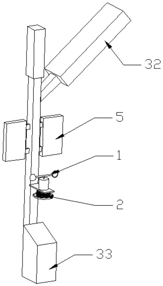
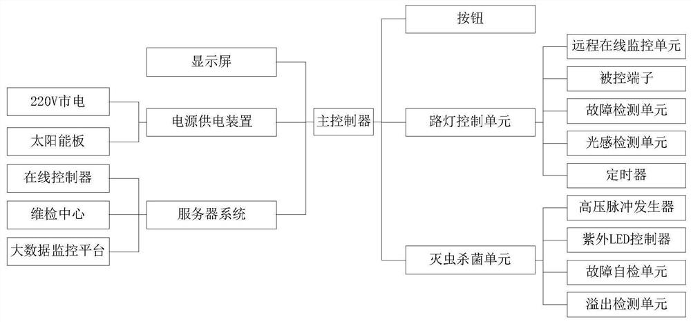
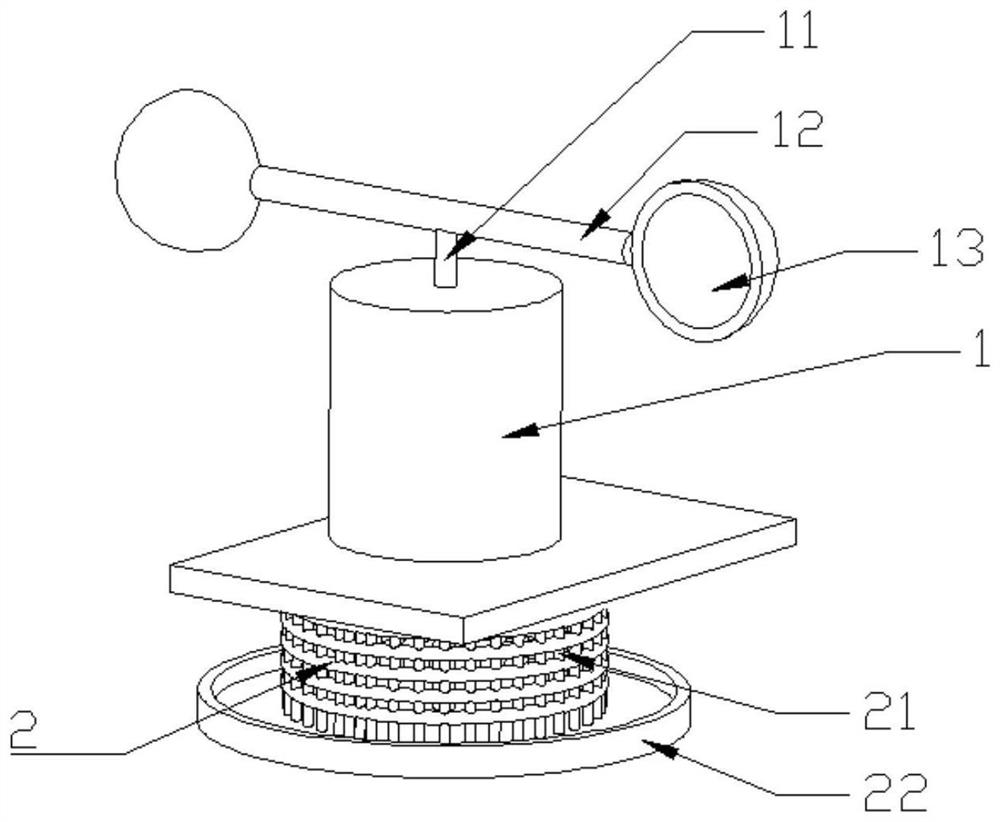

Image

  • A multi-functional integrated lighting and pest control system
  • A multi-functional integrated lighting and pest control system
  • A multi-functional integrated lighting and pest control system

Examples


Embodiment Construction

[0037] The following will clearly and completely describe the technical solutions in the embodiments of the present invention with reference to the accompanying drawings in the embodiments of the present invention. Obviously, the described embodiments are only some of the embodiments of the present invention, not all of them. Unless otherwise specified, the technical means used in the embodiments are conventional means well known to those skilled in the art.

[0038] In describing the present invention, it should be understood that the terms "longitudinal", "transverse", "upper", "lower", "front", "rear", "left", "right", "vertical", The orientations or positional relationships indicated by "horizontal", "top", "bottom", "inner", "outer", etc. are based on the orientations or positional relationships shown in the drawings, and are only for the convenience of describing the present invention, rather than indicating or It should not be construed as limiting the invention by impl...


PUM


Abstract

The present invention provides a multifunctional integrated lighting and pest control system, comprising: a power assembly, the power assembly includes a rotating shaft, a horizontal shaft and a wind catcher, the horizontal shaft and the rotating shaft are perpendicular to each other, and wind catchers are arranged at both ends of the horizontal shaft; Insect catching assembly, the insect catching assembly includes an insect catching net, the insect catching net is ring-shaped, and is connected with the rotating shaft, the rotation of the rotating shaft can drive the insect catching net to rotate; the insect catching assembly, the insect catching assembly includes an insect-killing lamp, and the insect-killing lamp is arranged on the The inside of the bug net. The method of using new LED lighting phosphors and lamination method to produce high-voltage output achieves the effect of lure by light and killing by high-voltage power grid, and realizes the functions of "green prevention and control" lighting, insecticide, sterilization, disinfection, etc. At the same time, this system combines the functions of the product A billboard is added to the appearance design, which makes the product appearance more beautiful and increases advertising revenue at the same time, realizing a multi-functional integrated lighting equipment that is energy-saving, environmentally friendly, efficient, beautiful and practical.

Description

technical field [0001] The invention belongs to the field of outdoor disinsection equipment, and in particular relates to the improvement of the structure of the disinsection equipment. Background technique [0002] Insecticidal lamp is a special device based on the phototaxis of insects, using insect-sensitive light sources in specific spectral ranges to trap insects and effectively kill insects, reduce the index of diseases and insect pests, and prevent and control insect pests and insect-borne diseases. [0003] At present, the high-voltage power grid of the equipment cannot be cleaned automatically, and it is easy to be stained with pests, rusted, and easily damaged, which seriously affects the insecticidal effect. In addition, the existing insecticidal lamps need to be connected to the mains, and the usage scenarios are limited by the wiring of the power grid. [0004] In addition, the insect-receiving bags currently equipped with most machines are made of cloth. The w...

Claims


Application Information

Patent Timeline
Patent Type & Authority Patents(China)
IPC IPC(8): A01M1/04A01M1/22H02J7/35B08B1/04G08C17/02F21S9/03F21V23/04F21V33/00F21V17/16F21V21/30F21V15/01F21Y115/10
CPCA01M1/04A01M1/223H02J7/35B08B1/04G08C17/02F21S9/035F21V23/0457F21V33/00F21V17/164F21V21/30F21V15/01F21Y2115/10
Inventor 刘瑶郭朝中刘代军靳娟廖文利李忠彬李国庆
Owner CHONGQING UNIV OF ARTS & SCI
Why Eureka
Try Eureka