Photoelectric integrated processing device and photoelectric integrated processing technique for waste gases generated by spraying paint

A technology for treating device and waste gas, which is applied in combination devices, chemical instruments and methods, and dispersed particle separation, etc., can solve problems such as troublesome activated carbon treatment, and achieve the effect of saving space, reducing equipment operating costs, and reducing usage.

Inactive Publication Date: 2015-10-07
杭州科瑞特环境技术有限公司
View PDF11 Cites 25 Cited by
  • Summary
  • Abstract
  • Description
  • Claims
  • Application Information

AI Technical Summary

Problems solved by technology

[0008] Activated carbon adsorption: direct adsorption of organic gases by activated carbon, this method has simple equipment, small investment, and conv

Method used


Image

  • Photoelectric integrated processing device and photoelectric integrated processing technique for waste gases generated by spraying paint
  • Photoelectric integrated processing device and photoelectric integrated processing technique for waste gases generated by spraying paint
  • Photoelectric integrated processing device and photoelectric integrated processing technique for waste gases generated by spraying paint

Examples


Embodiment 1

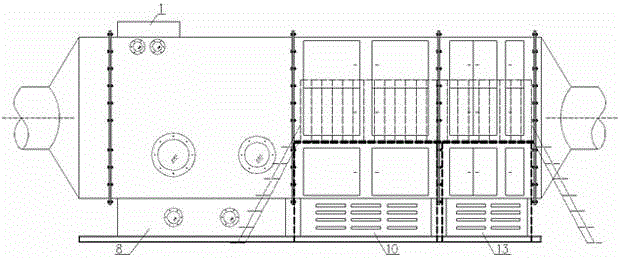
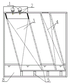
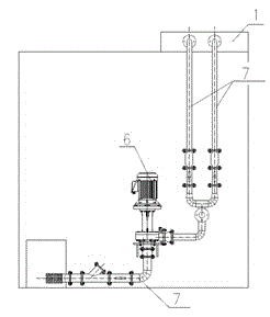
[0069] In this embodiment, the spray unit 3 of the exhaust gas treatment device has a filler height of 2080mm above the liquid level and a thickness of 960mm. The φ50 Taylor wreath is used as the filler, the liquid level is about 310mm, and the spray liquid dosage is 60m3 / h. There are two rows in total. Ten spray nozzles 2 are arranged on the blind plate 1 of the circulating liquid pipe flange, and the spray nozzles 2 are A3 type. The spray pipe 7 circulating liquid tank 8 and the vertical circulating pump 6 are connected by PP pipes, the main pipe diameter is 100mm, the straight pipe diameter is 65mm, the middle is adjusted and switched by the ball valve and the check valve, and the circulating liquid tank 8 is at the outlet Set Y-type filter and grease trap to remove paint residue, etc. The height of the filler of the demister unit 4 above the liquid level is 2380mm, the thickness is 400mm, and the φ25 Pall ring is used as the filler. The size of a single module of the plasm...

Embodiment 2

[0074] In this device, the spray liquid dosage is 40m3 / h, the spray pipe 7 has a diameter of 65mm, the branch pipe has a diameter of 50mm, and the bottom liquid level is 180mm. The design of the rest of the device is the same as in Example 1. The source of the exhaust gas is the painting exhaust gas of a mold processing factory.

[0075] In this embodiment, the design air volume is 20000m3 / h, the air inlet interface size of the equipment is 1840×2280mm, the design exhaust gas flow rate is 1.3m / s, and the main components of the exhaust gas are methyl isobutyl ketone, diisobutyl ketone, and methyl ethyl ketone. Wait, the temperature is normal temperature. The content of pollutants in and out of exhaust gas is as follows:

[0076] Table 2 Concentration of pollutants in the exhaust gas in and out of Example 2

[0077]

Embodiment 3

[0079] The design of this device is the same as that of Example 1, and the source of exhaust gas is mold coating.

[0080] In this embodiment, the design air volume is 30000m3 / h, the air inlet interface size of the equipment is 1840×2280mm, the design exhaust gas flow rate is 2m / s, the main components of the exhaust gas are toluene, xylene, ethyl acetate, etc., and the temperature is normal temperature. The content of pollutants in and out of exhaust gas is as follows:

[0081] Table 3 Concentrations of pollutants in the exhaust gas in and out of Example 3

[0082] .


PUM


Abstract

The invention discloses a photoelectric integrated processing device and a photoelectric integrated processing technique for waste gases generated by spraying paint. A washing processing unit, a low-temperature plasma processing unit and a photocatalytic processing unit are arranged inside a device casing and are sequentially connected. The photoelectric integrated processing technique comprises the following steps that the waste gases generated by spraying paint enter the washing processing unit through a pipeline for spraying at first to remove particulate matters in the waste gases generated by spraying paint; the waste gases generated by spraying paint then enter into a demisting unit for further removing paint mist; the waste gases generated by spraying paint are discharged into a plasma module for oxidizing organic matters in the gases; finally, the waste gases generated by spraying paint enter the photocatalytic processing unit, and by taking a carbon fiber adsorption layer as a catalytic carrier, the organic matters adsorbed in carbon fiber pores are oxidized and decomposed by using an ultraviolet lamp tube. According to the equipment, an absorption method, a low-temperature plasma technology, a photocatalytic technique and an activated carbon adsorption technique are effectively combined, so that the problems of secondary pollution, shorter operation cycle, short operation life and the like existing in single technique are solved while the treatment efficiency of the waste gases is improved.

Description

Technical field [0001] The invention belongs to the field of waste gas treatment, and specifically relates to a photoelectric integrated treatment device and process for paint spray waste gas. Background technique [0002] In the painting process of painting, furniture, vehicle and ship manufacturing, and electrical components, the paint used for spraying will generate a large amount of volatile organic waste gas (VOCs), and the main components are esters, olefinic acids, alkyds, aromatic hydrocarbons, etc. , Disorganized emission in the workshop will threaten human health. At present, the treatment of spraying waste gas mainly adopts absorption method, condensation method, photocatalysis method, direct combustion method, catalytic combustion method, adsorption method, etc. [0003] Absorption method: The absorption method is widely used in the treatment of spray paint waste gas. The principle is to spray water into the waste gas to promote the dissolution and sedimentation of wat...

Claims


Application Information

Patent Timeline
IPC IPC(8): B01D50/00B01D53/75B01D53/04
Inventor 邵振华金奇超邓方睿姜建清
Owner 杭州科瑞特环境技术有限公司
Why Eureka
Try Eureka