Cooling circulation system for electric vehicles, and electric vehicle with cooling circulation system

An electric vehicle and circulation system technology, applied in the field of vehicles, can solve the problems of reduced working efficiency of the cooling circulation system, and achieve the effects of reducing loss, increasing cooling flow, and shortening cooling pipelines

Active Publication Date: 2015-10-07
BEIQI FOTON MOTOR CO LTD
View PDF4 Cites 13 Cited by
  • Summary
  • Abstract
  • Description
  • Claims
  • Application Information

AI Technical Summary

Problems solved by technology

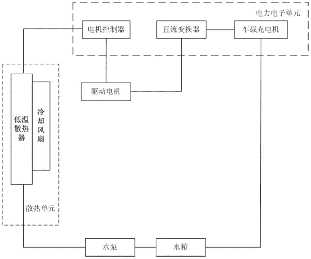
However, in the cooling circulation system of the prior art, no matter in various modes such as charging or driving, the coolant flows through the motor controller, drive motor, DC converter, and on-board charger in sequence, which will cause unnecessary losses , resulting in a reduction in the efficiency of the cooling cycle system

Method used


Image

  • Cooling circulation system for electric vehicles, and electric vehicle with cooling circulation system
  • Cooling circulation system for electric vehicles, and electric vehicle with cooling circulation system
  • Cooling circulation system for electric vehicles, and electric vehicle with cooling circulation system

Examples


Embodiment Construction

[0019] Embodiments of the present invention are described in detail below, examples of which are shown in the drawings, wherein the same or similar reference numerals designate the same or similar elements or elements having the same or similar functions throughout. The embodiments described below by referring to the figures are exemplary only for explaining the present invention and should not be construed as limiting the present invention.

[0020] In describing the present invention, it should be understood that the terms "center", "longitudinal", "transverse", "upper", "lower", "front", "rear", "left", "right", " The orientations or positional relationships indicated by "vertical", "horizontal", "top", "bottom", "inner", "outer", etc. are based on the orientation or positional relationships shown in the drawings, and are only for the convenience of describing the present invention and simplifying Describes, but does not indicate or imply that the device or element referred...


PUM


Abstract

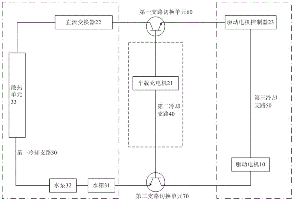
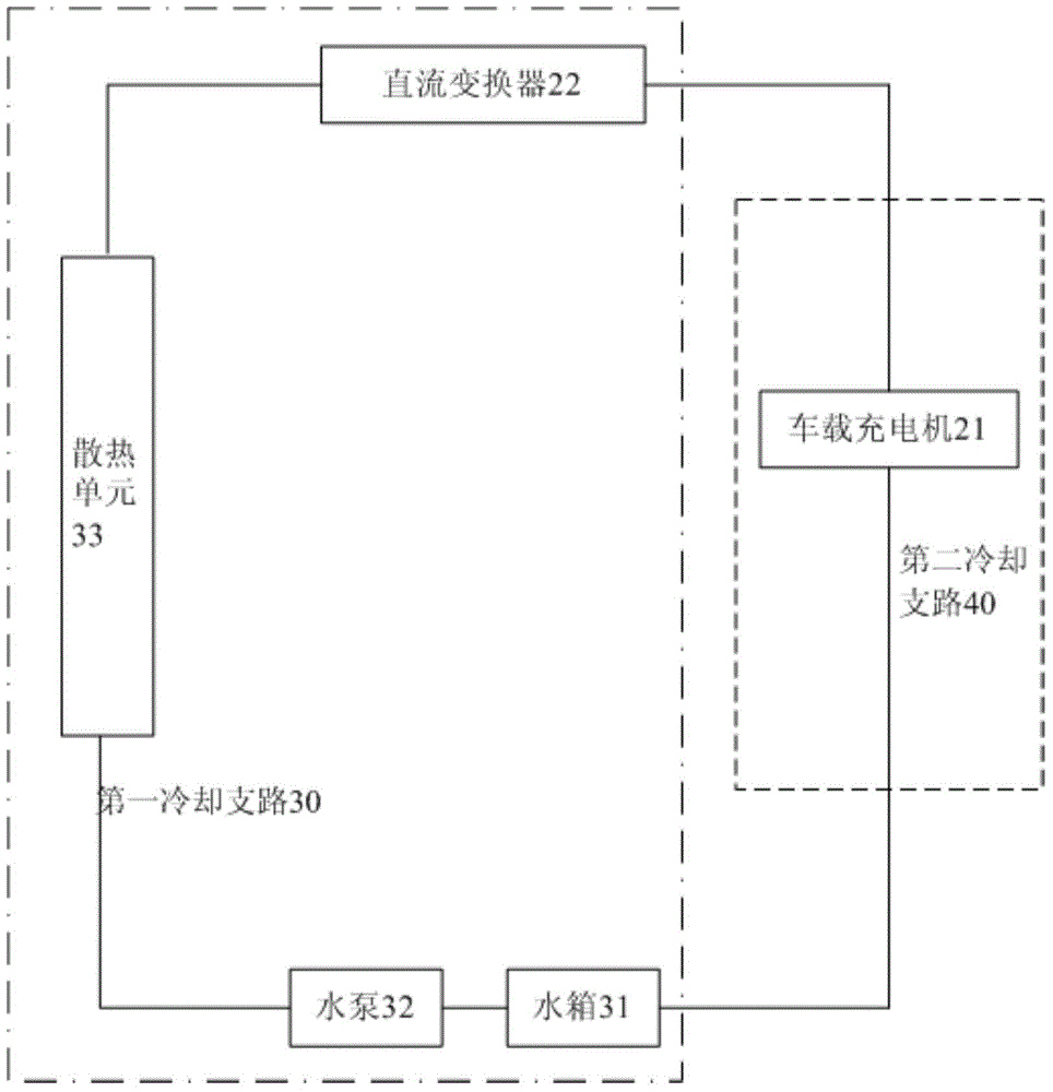
The invention discloses a cooling circulation system for electric vehicles, and an electric vehicle with the cooling circulation system. The cooling circulation system of the electric vehicle comprises a driving motor, a power electronic unit, a first cooling branch, a second cooling branch, a third cooling branch, a first branch switching unit and a second branch switching unit. According to the cooling circulation system for electric vehicles, and the electric vehicle with the cooling circulation system, which are disclosed by the embodiment of the invention, the first branch switching unit and the second branch switching unit are arranged in the cooling circulation system, and the switching between the first branch switching unit and the second branch switching unit is controlled, so that the switching of cooling loops under different modes can be realized; only parts in a working state under a corresponding mode need to be cooled, and the cooling of all parts is not needed, so that unnecessary consumption is reduced; besides, a cooling pipeline is shortened, and the cooling flow is increased, so that the working efficiency of the cooling circulation system is improved.

Description

technical field [0001] The invention relates to the technical field of vehicles, in particular, to a cooling cycle system for an electric vehicle and an electric vehicle having the same. Background technique [0002] At present, electric vehicles mostly adopt decentralized design schemes, and their cooling circulation systems are mostly designed with a single series pipeline. Specifically, such as figure 1 As shown, the cooling cycle system may include a motor controller (MCU), a drive motor, a DC converter (DC / DC), an on-board charger (OBC), a water tank, a water pump, and a cooling unit (cooling fan and low-temperature radiator), which will The above components are connected in series to form a cooling circulation system of a circulation loop. When cooling the vehicle system, the water pump starts to work, so that the coolant can flow through the motor controller, drive motor, DC converter, and on-board charger in order to cool the above components. [0003] However, wi...

Claims


Application Information

Patent Timeline
Patent Type & Authority Applications(China)
IPC IPC(8): B60K11/02H02K9/19
Inventor 张艳超
Owner BEIQI FOTON MOTOR CO LTD
Why Eureka
Try Eureka