Optical lens

An optical lens and lens technology, applied in the field of optical lenses, can solve the problems of low light conversion efficiency, poor spot uniformity, discontinuous light, etc., so as to improve the spot uniformity and light utilization rate, high light conversion efficiency, The effect of a large light angle

Inactive Publication Date: 2015-10-07
郭萌
View PDF7 Cites 7 Cited by
  • Summary
  • Abstract
  • Description
  • Claims
  • Application Information

AI Technical Summary

Problems solved by technology

In the prior art, there is also a lens that can make the LED light source form a square spot. For example, the Chinese invention patent document with the application number 201410540343.7 discloses a LED multi-faceted light-emitting plane light source. The optical lens can make the LED light source produce a square spot. However, d

Method used


Image

  • Optical lens
  • Optical lens
  • Optical lens

Examples


Embodiment 1

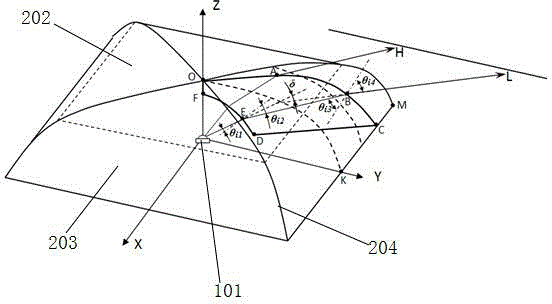
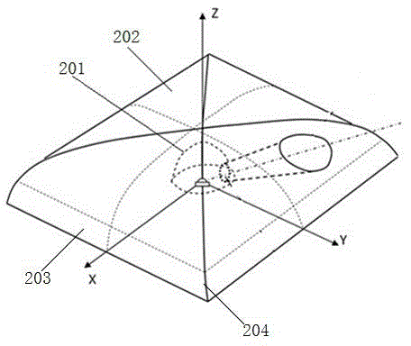
[0038] Such as figure 1 with figure 2As shown, an optical lens includes a convex light incident surface 201, a light exit surface 202, four corner surfaces 204 and four sides 203, and the four sides 203 are arranged in a square on four sides of the light exit surface 202. The four corner surfaces 204 are respectively located at the four corners of the square for refracting or reflecting light, the concave lens is located at the center of the square, the light exit surface 202, the four corner surfaces 204 and The four sides 203 are smoothly connected to form a continuous smooth curved surface in the shape of a cover.

[0039] The hood-shaped continuous smooth curved surface is divided into a first part OA, a second part AB and a third part BC from the center to the outside, and the incident angle k of the light rays entering the air through the first part OA and the second part AB 1 meet k 1 =15°~22°, the incident angle k of incident air through the third part BC 2 meet ...

Embodiment 2

[0053] Such as figure 1 with figure 2 As shown, an optical lens includes a convex light incident surface 201, a light exit surface 202, four corner surfaces 204 and four sides 203, and the four sides 203 are arranged in a square on four sides of the light exit surface 202. The four corner surfaces 204 are respectively located at the four corners of the square for refracting or reflecting light, the concave lens is located at the center of the square, the light exit surface 202, the four corner surfaces 204 and The four sides 203 are smoothly connected to form a continuous smooth curved surface in the shape of a cover.

[0054] The hood-shaped continuous smooth curved surface is divided into a first part OA, a second part AB and a third part BC from the center to the outside, and the incident angle k of the light rays entering the air through the first part OA and the second part AB 1 meet k 1 =15°~22°, the incident angle k of incident air through the third part BC 2 meet...


PUM


Abstract

The invention discloses an optical lens. The optical lens comprises a light inlet surface, a light outlet surface, four corner surfaces and four side surfaces, wherein the light inlet surface is convex; the four side surfaces are arranged at the four sides of the light outlet surface in a square form; the four corner surfaces are respectively positioned at four corners of the square, and are used for refracting or reflecting light rays; a concave lens is positioned in the center of the square; and the light outlet surface, the four corner surfaces and the four side surfaces are smoothly connected to form a cover-shaped continuous smooth curved surface. The optical lens can enable an LED light source to generate square light spots; the light spots are large in light emitting angles; and the light ray conversion efficiency is high.

Description

technical field [0001] The invention relates to the field of semiconductor lighting, in particular to an optical lens. Background technique [0002] The light source emitted by the LED is a Lambertian light source. Usually, the luminous angle is 120°. The characteristic of the Lambertian light source is that the light near the center is dense, and the light far away from the center is sparse. Therefore, in practical applications, the illuminance of the light spot formed by the LED light source It is very uneven, so in semiconductor lighting technology, it is often necessary to carry out secondary optical design on LED light source. In the prior art, there have been technologies for secondary optical design of the LED light source so that the LED light source finally forms a rectangular light spot. These technologies mainly focus on the application of LED street lights to make the LED street light produce a rectangular light spot. For example, the application numbers are 2011...

Claims


Application Information

Patent Timeline
IPC IPC(8): F21V5/04F21Y101/02
CPCF21V5/04
Inventor 郭萌
Owner 郭萌
Why Eureka
Try Eureka