Multifrequency operation wireless power transfer transmitting terminal circuit

A technology of wireless energy transmission and transmitting end, applied in the direction of electromagnetic wave system, etc., can solve the problems of repeated waste of adapters, unfavorable energy saving and environmental protection, etc., and achieve the effect of avoiding repeated waste and reducing the quantity

Inactive Publication Date: 2015-10-07
FUJIAN UNIV OF TECH
View PDF6 Cites 19 Cited by
  • Summary
  • Abstract
  • Description
  • Claims
  • Application Information

AI Technical Summary

Problems solved by technology

As a result, different types of terminals require different transmitters for adaptation, resulting in repeated waste of adapters, which is not conducive to energy saving and environmental protection

Method used


Image

  • Multifrequency operation wireless power transfer transmitting terminal circuit
  • Multifrequency operation wireless power transfer transmitting terminal circuit
  • Multifrequency operation wireless power transfer transmitting terminal circuit

Examples


Embodiment

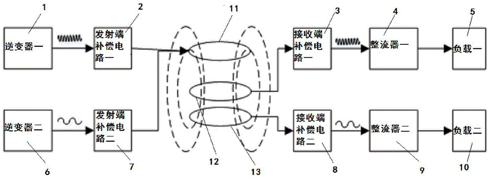
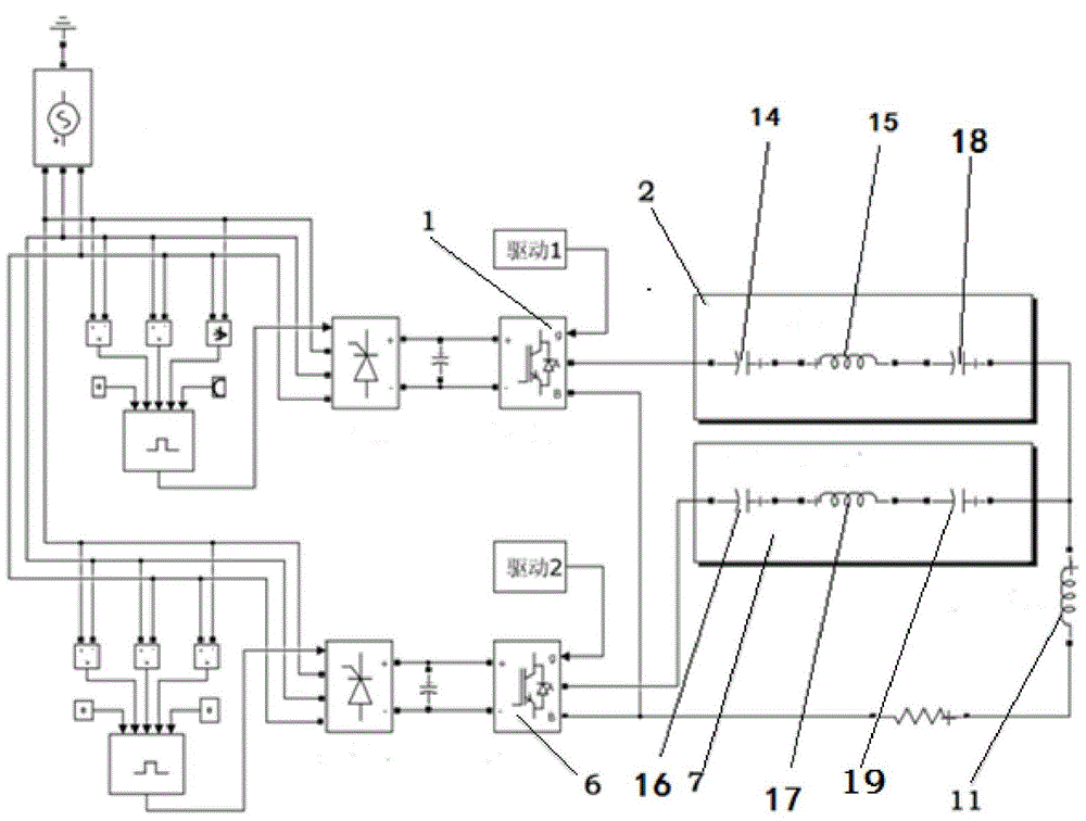
[0021] Such as Figure 2-6 The wireless power transmission transmitting end circuit shown as a multi-frequency operation includes a transmitting coil 11 and two receiving coils. The two receiving coils are receiving coil one 12 and receiving coil two 13, respectively. Two transmitting coils 12 are connected. Parallel transmitting circuit, one transmitting circuit includes inverter-1 that converts direct current into high-frequency alternating current, and inverter-1 is connected with transmitting end compensation circuit-2 that synthesizes high-frequency alternating current; the other transmitting circuit includes Inverter 2 6 converts direct current into low frequency alternating current. Inverter 2 6 is connected with transmitting end compensation circuit 2 7 that synthesizes low frequency alternating current; transmitting end compensation circuit 1 2 and transmitting end compensation circuit 2 7 are connected in parallel with the transmitting coil 11 connection; after receiv...


PUM


Abstract

The invention discloses a multifrequency operation wireless power transfer (WPT) transmitting terminal circuit, comprising a transmitting coil and at least two receiving coils. The transmitting coil is in connection with a plurality of transmission circuits; each transmission circuit comprises an inverter or converting direct current into alternating current; the inverter is in connection with a transmitting terminal compensating circuit for synthesizing alternating current; the frequencies of the alternating current emitted by the inverters are different so as to adapt for different transmission distances. The transmitting coil can operate at different frequency points at the same time or at different time; when a coupling coil is closer, a system works in a low frequency close range mode so as to adapt for terminals with receiving terminals of lower work frequency, and when a coupling coil is farther, the system works in a high frequency middle range mode so as to adapt for terminals having receiving terminals of higher work frequency. The transmitting terminal circuit can meanwhile adapt for receiving terminal circuits of different work frequencies so as to reduce transmitting terminals, and avoid repetition and waste of wireless charging transmitting terminals.

Description

Technical field [0001] The invention belongs to the field of electrical devices, and in particular relates to a wireless power transmission transmitting end circuit with multi-frequency operation. Background technique [0002] Near-field magnetic coupling wireless power transfer technology (Wireless Power Transfer, WPT) is an emerging power transmission technology that uses electromagnetic induction between coupling coils to achieve wireless power transmission. Compared with traditional wired power transmission, wireless power transmission technology has the advantages of safety, reliability, convenience, and strong environmental adaptability. The structure of the near-field magnetic coupling wireless power transmission system is as follows figure 1 As shown, the system mainly includes a high-frequency inverter at the transmitting end, a coupling coil and its compensation network, and a rectifier and voltage regulator circuit at the receiving end. [0003] In recent years, with th...

Claims


Application Information

Patent Timeline
Patent Type & Authority Applications(China)
IPC IPC(8): H02J17/00
Inventor 林抒毅郑荣进蒋新华谢文明黄诗浩聂明星邵明
Owner FUJIAN UNIV OF TECH
Why Eureka
Try Eureka