Check patentability & draft patents in minutes with Patsnap Eureka AI!

A Method for Optical Axis Fixing of Cylindrical Mirror

A cylindrical mirror and optical technology, used in turning equipment, measuring/indicating equipment, auxiliary devices, etc., can solve the problems of scratching the optical axis reference accuracy of optical components, and achieve the effect of ensuring coincidence accuracy

Inactive Publication Date: 2017-05-31
XI'AN INST OF OPTICS & FINE MECHANICS - CHINESE ACAD OF SCI
View PDF5 Cites 0 Cited by
  • Summary
  • Abstract
  • Description
  • Claims
  • Application Information

AI Technical Summary

Problems solved by technology

[0007] In order to solve the technical problems such as the existing method of determining the optical axis reference of a cylindrical mirror that easily leads to scratches on optical elements and low accuracy of the optical axis reference, the present invention provides a method and equipment for optical axis-fixed processing of a cylindrical mirror

Method used


Image

  • A Method for Optical Axis Fixing of Cylindrical Mirror
  • A Method for Optical Axis Fixing of Cylindrical Mirror

Examples


Embodiment Construction

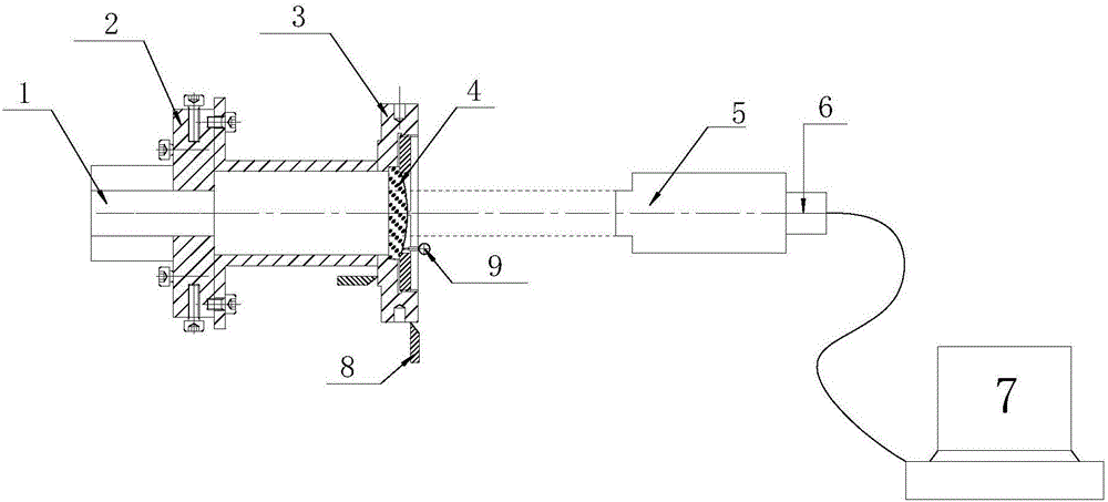
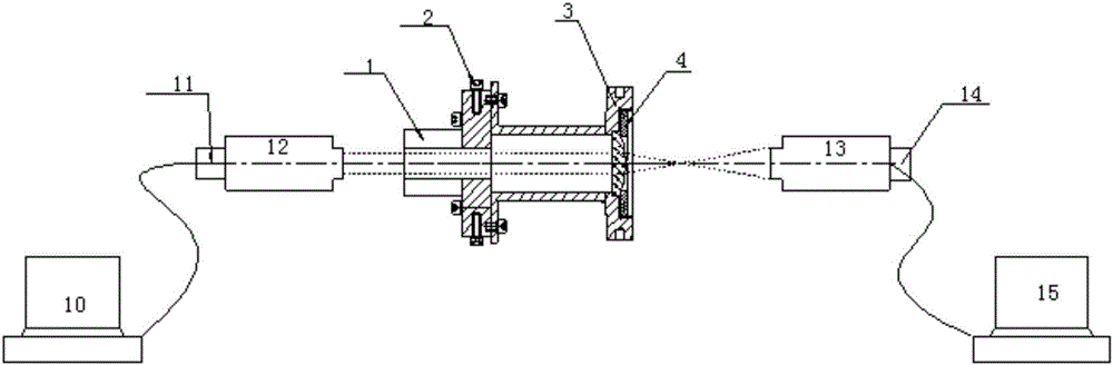
[0026] like figure 1 The cylindrical mirror optical axis fixing system shown includes attitude adjustment tooling 2, mirror frame 3, first optical centering device 12, second optical centering device 13, first CCD camera 11, second CCD camera 14, first PC 10 and the second PC 15;

[0027] The attitude adjustment tool is fixed on the rotation axis 1 of the lathe, the mirror frame is fixed on the attitude adjustment tool, and a cylindrical mirror is fixed inside the mirror frame. The first optical centering device is located at one end of the rotation axis of the lathe and faces the plane of the cylindrical mirror. The centering device is connected to one end of the first CCD camera, and the other end of the first CCD camera is connected to the first PC; the second optical centering device is located directly in front of the exit window of the frame, and the second optical centering device faces the cylindrical surface The cylindrical surface of the mirror, the second optical c...


PUM


Abstract

The invention relates to a cylindrical mirror optical fixed-axis system and a cylindrical mirror optical fixed-axis method, wherein the system comprises a posture adjustment tool, a mirror frame, a first optical centrescope, a second optical centrescope, a first CCD (charge coupled device) camera, a second CCD camera, a second PC (personal computer) and a second PC, wherein the posture adjustment tool is fixed on a lathe rotating shaft; the mirror frame is fixed on the posture adjustment tool; a cylindrical mirror is fixed in the mirror frame; the first optical centrescope is positioned at one end of the lathe rotating shaft, and faces towards the plane of the cylindrical mirror; the first optical centrescope is connected with one end of the first CCD camera; and the other end of the first CCD camera is connected with the first PC. In order to solve the technical problems that a current method for determining cylindrical mirror optical axis reference is liable to cause optical element scratch, low in optical-axis reference precision and the like, the cylindrical mirror optical fixed-axis system completely adopts an optical non-contact type measuring mode, so that the coincident accuracy of the optical axis and a mechanical rotary shaft is guaranteed.

Description

technical field [0001] The invention belongs to the field of optical axis fixing, in particular to a method for determining the optical axis of a cylindrical mirror. Background technique [0002] Cylindrical lens is a special case of aspheric surface, which has special optical imaging characteristics. High-precision cylindrical mirrors and cylindrical system online focusing systems, movie camera lenses, laser printers, etc. are more and more widely used. These applications require corresponding high-precision adjustment methods to ensure the consistency of the optical axis of the optical system. [0003] Imaging characteristics of the cylindrical lens: Because the cylindrical lens is not rotationally symmetric, the cylindrical lens has no spherical center point, only the spherical center line. A plane wave passing through a cylindrical lens will not form a focal point, but will form a focal line. Theoretically, there is no so-called optical axis in cylindrical mirrors, but...

Claims


Application Information

Patent Timeline
Patent Type & Authority Patents(China)
IPC IPC(8): B23B25/06B23Q17/24
CPCB23B25/06B23Q17/2419B23Q17/2428
Inventor 付兴杜琛王鹏宋冲侯晓华
Owner XI'AN INST OF OPTICS & FINE MECHANICS - CHINESE ACAD OF SCI
Features
  • R&D
  • Intellectual Property
  • Life Sciences
  • Materials
  • Tech Scout
  • Unparalleled Data Quality
  • Higher Quality Content
  • 60% Fewer Hallucinations
Learn More