Timber saw blade cutting machine

A cutting machine and saw blade technology, applied in the field of wood saw blade cutting machines, can solve the problems of inability to change the horizontal distance, affect the operation performance, and cannot move, so as to reduce the waste of wood resources, reduce the probability of deviation, and have good effect Effect

Inactive Publication Date: 2015-10-14
JIANGSU DONGJIA WOOD IND
View PDF1 Cites 1 Cited by
  • Summary
  • Abstract
  • Description
  • Claims
  • Application Information

AI Technical Summary

Problems solved by technology

[0002] The saw blade cutting machine is a traditional cutting and cutting equipment for wood processing. Since the general saw blade cutting machine does not have a device for pressing the workpiece, long pieces of wood are prone to offset and twist during the processing operation, which affects the operating performance and makes the wood Serious waste, aggravating resource consumption
The Chinese publication number is CN203357568U, and the patent titled "Wood Processing and Cutting Machine" discloses the technical scheme of "the rotatable pressure roller of the cutting machine applies a force in the vertical direction to the wood to prevent the wood from shifting during cutting", but the There are deficiencies in the specific implementation of the technical solution, that is, the two pressure rollers located above the wood can only move in the vertical direction and cannot move in the horizontal direction, that is to say, the horizontal distance between the two pressure rollers cannot be changed
If the diameter of the wood is too large, the two pressure rollers will be too close, and the force will be concentrated on the upper surface of the wood, and the force effect will not be good; if the diameter of the wood is too small, the distance between the two pressure rollers will be too far, and there will be no contact with the wood. Cannot apply vertical force

Method used


Image

  • Timber saw blade cutting machine

Examples


Embodiment Construction

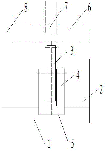
[0008] Such as figure 1 As shown, the wood saw blade cutting machine includes a base 1, an operating platform 2 is arranged on the base 1, a saw blade 3 is arranged on the operating platform, the saw blade 3 is fixed on a bearing frame 4, and the bottom block of the bearing frame is placed on the base Inside the provided chute 5, and move along the direction of the chute 5, the direction of the chute 5 is the same as that of the saw blade 3. The bottom block of the bearing frame slides in the base chute 5, driving the saw blade 3 to move horizontally, thereby adjusting the horizontal distance between the wood 6, the two pressure rollers 7 and the saw blade 3, so that the two pressure rollers 7 are located above the wood Best location.

[0009] One side of the console 2 is also provided with a fixed baffle 8 along the direction of the saw blade, which is used to fix the wood axially and further prevent the wood from twisting.


PUM


Abstract

The invention discloses a timber saw blade cutting machine comprising a pedestal and an operation table arranged on the pedestal; the operation table is provided with a saw blade fixed on a bearing rack; a bearing rack bottom piece is placed in a pedestal slide slot and moves in the slide slot; the slide slot and the saw blade are in a same direction. One side of the operation table is vertically provided with a fixed stop plate having same direction with the saw blade. The bearing rack bottom piece can slide in the pedestal slide slot so as to drive the saw blade to move in a horizontal direction, thus adjusting horizontal distances between timbers, two pressure rollers and the saw blade, so the two pressure rollers can be in best force application positions above the timber; the timber saw blade cutting machine is best in effect, most convenient in operation, thus reducing timber offset probability, and reducing timber resource waste.

Description

technical field [0001] The invention relates to wood processing equipment, in particular to a wood saw blade cutting machine. Background technique [0002] The saw blade cutting machine is a traditional cutting and cutting equipment for wood processing. Since the general saw blade cutting machine does not have a device for pressing the workpiece, long pieces of wood are prone to offset and twist during the processing operation, which affects the operating performance and makes the wood The phenomenon of waste is serious and increases resource consumption. The Chinese publication number is CN203357568U, and the patent titled "Wood Processing and Cutting Machine" discloses a technical scheme of "the rotatable pressure roller of the cutting machine exerts a vertical force on the wood to prevent the wood from shifting during cutting", but the There are deficiencies in the specific implementation of the technical solution, that is, the two pressure rollers above the wood can onl...

Claims


Application Information

Patent Timeline
Patent Type & Authority Applications(China)
IPC IPC(8): B27B5/18
CPCB27B5/181
Inventor 石智慧
Owner JIANGSU DONGJIA WOOD IND
Why Eureka
Try Eureka