A temperature decoupling master-slave control method for multiple heating zones

A control method and heating zone technology, applied in heat treatment process control, manufacturing tools, heat treatment equipment, etc., can solve problems such as poor temperature uniformity, weak anti-disturbance ability, and inconvenient operation, and achieve low cost, convenient operation, and simplified strength Effect

Active Publication Date: 2017-07-28
CHENGDU AIRCRAFT INDUSTRY GROUP
View PDF1 Cites 0 Cited by
  • Summary
  • Abstract
  • Description
  • Claims
  • Application Information

AI Technical Summary

Problems solved by technology

[0006] The purpose of the present invention is mainly aimed at the disadvantages of the traditional multi-heating zone multi-instrument independent control method, which brings to the system poor temperature uniformity, weak anti-disturbance ability, high cost, and inconvenient operation. And embedded digital decoupling controller, good temperature uniformity, strong anti-disturbance ability, low cost, good flexibility, easy to operate control method

Method used


Image

  • A temperature decoupling master-slave control method for multiple heating zones
  • A temperature decoupling master-slave control method for multiple heating zones
  • A temperature decoupling master-slave control method for multiple heating zones

Examples


Embodiment 1

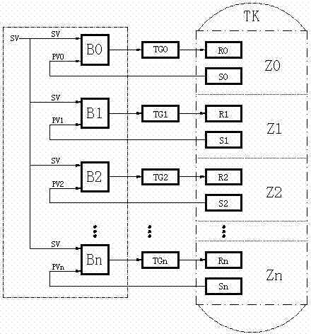
[0028] A multi-heating zone temperature decoupling master-slave control method is characterized in that it comprises the following steps:

[0029] The first step is to measure m different temperature points (ie, SV S0 、SV S1 ,...,SV Sm-1 ) temperature uniformity, and make the uniformity curve of each temperature measurement point, record the actual temperature of the steady state of n heating zones under the corresponding temperature measurement point (ie PV 0S0 、PV 0S1 ,...,PV 0Sm-1 ; PV 1S0 、PV 1S1 ,...,PV 1Sm-1 ;…;PV n-1S0 、PV n-1S1 ,...,PV n-1Sm-1 ;);

[0030] The second step is to determine m different temperature measurement points as typical temperature coupling points in each temperature zone, and set n 2×m dimensional decoupling arrays (VC) based on the temperature uniformity of the coupling points, each of which is decoupled The m elements in the first column of the array are the temperatures of the m temperature measurement points (ie SV S0 、SV S1 ,...,...

Embodiment 2

[0034] The present invention will be further described below in conjunction with the accompanying drawings and the examples. This example mainly uses a 3-temperature zone system (ie n=3) and 8 temperature uniformity detection points (ie m=8) to illustrate, and uses the 0th heating The zone is the main temperature control zone, the first heating zone is the slave control zone, and the second heating zone is the slave control zone, but this does not limit the present invention to the scope of the described embodiments.

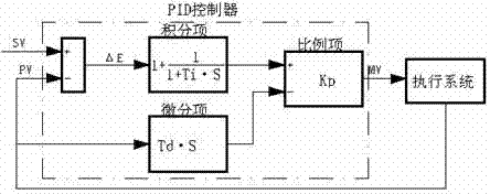
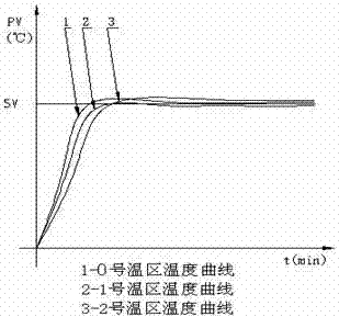
[0035] see image 3 , Figure 4 , Figure 5 and Image 6

[0036] exist Figure 5 Middle SV—set temperature, PVB—decoupling output value, SV1—set temperature after decoupling, VC—decoupling vector, decoupling vector (VC) is a 2×8-dimensional real array, stored in the first column The temperature of 8 temperature measuring points, the second column stores 8 steady-state temperatures corresponding to the temperature measuring points, so that the temperature c...


PUM


Abstract

The invention relates to a temperature decoupling master-slave control method for multiple heating zones. The method is to measure the uniformity curves of m temperature points; according to the uniformity curves of m temperature points, n 2×m dimensional decoupling arrays are set to form n decoupling vectors; determine n temperature coupling curves according to the m coupling points of the n decoupling vectors; calculate the decoupling compensation amount (PVB) at the corresponding temperature point according to the n coupling curves, and then compare with the set value SV After adding, the new set temperature (SV1) of each zone is obtained; the new set temperature (SV1) and the feedback temperature PV of each zone are sent to the PID operation controller for calculation, and then the output is adjusted to the execution unit for temperature adjustment. This method costs Low, simple, very convenient parameter adjustment, high uniformity and stability of temperature control, can be widely used in vacuum furnaces, air circulation electric furnaces, etc.

Description

technical field [0001] The invention belongs to the field of temperature decoupling control in automatic control technology, and in particular relates to a temperature decoupling master-slave control method for multiple heating zones. Background technique [0002] At present, with the advancement of science and technology, there are more and more heat treatment equipment, especially large heat treatment equipment, such as vacuum furnace, atmosphere furnace, air circulation electric furnace, etc. However, most of this type of equipment is usually controlled by multiple temperature zones, and each temperature control zone is equipped with at least one temperature control instrument, and each instrument controls the temperature of each zone independently by setting the same set value. [0003] like figure 1 Shown: B0—the temperature control instrument of No. 0 partition, B1—the temperature control instrument of No. 1 partition, B2—the temperature control instrument of No. 2 pa...

Claims


Application Information

Patent Timeline
Patent Type & Authority Patents(China)
IPC IPC(8): C21D11/00
Inventor 高猛
Owner CHENGDU AIRCRAFT INDUSTRY GROUP
Why Eureka
Try Eureka