Method For The Construction Of An Led Light Module

A technology for LED modules and light-emitting modules, which is applied to semiconductor devices of light-emitting elements, light sources, electric light sources, etc., can solve problems such as inability to adjust additional optical devices.

Inactive Publication Date: 2015-10-14
HELLA KG HUECK & CO
View PDF7 Cites 3 Cited by
  • Summary
  • Abstract
  • Description
  • Claims
  • Application Information

AI Technical Summary

Problems solved by technology

In this structure of the LED lighting module, it is also not possible to adjust the additional optical device relative to the LED lighting device accommodated on the circuit board.

Method used


Image

  • Method For The Construction Of An Led Light Module
  • Method For The Construction Of An Led Light Module
  • Method For The Construction Of An Led Light Module

Examples


Embodiment Construction

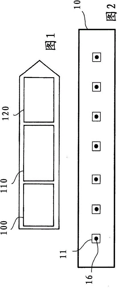
[0029] figure 1 The flow of the method for constructing the LED lighting module according to the present invention is shown in a schematic diagram. Said method comprises as an important method step of the present invention: first LED lighting device is arranged 100 on the circuit board, wherein method step setting 100 can comprise for example at least one soldering process, and said LED lighting device is constructed as SMD component, so that can Soldered on the mounting surface of the circuit board.

[0030] As a further method step, it is provided that the position of the LED luminous means in the X-Y plane on the circuit board is measured 110 . This measuring method step 110 is carried out, for example, by an optical measuring device, in particular by a camera. The method steps of producing more than 120 holes in the circuit board are then carried out.

[0031] The production 120 of the bore can be carried out, for example, by means of a milling process with a cutting to...


PUM


Abstract

A method for the construction an LED light module, having a printed circuit board, on which at least one LED lamp is accommodated, and having at least one optical element, into which the light generated by the LED lamp can be emitted, wherein the optical element has mounting pins and wherein holes are formed in the printed circuit board, such that the optical element is arranged on the printed circuit board by an insertion of the mounting pins in the holes, wherein the method comprises at least the following steps: arrangement of at least one LED lamp on a mounting surface of the printed circuit board, measurement of the position of the LED lamp in the plane of the mounting surface of the printed circuit board, creation of the holes in the printed circuit board at a position that is dependent on the measured position of the LED lamp in the plane of the mounting surface, and arrangement of the optical element on the printed circuit board by means of an insertion of the mounting pins in the holes.

Description

technical field [0001] The invention relates to a method for constructing an LED (Light Emitting Diode) lighting module, said LED lighting module having a circuit board on which at least one LED lighting device is accommodated, said LED lighting module also having at least one optical The light that can be generated by the LED light emitting device can enter the optical element, the optical element has receiving pins, and a plurality of holes are introduced in the circuit board, so that the optical element can be inserted into the optical element by inserting the receiving pins. The holes are set on the circuit board. [0002] An LED lighting module here refers to all structural units which are intended for emitting light and which can preferably be installed in the housing of a headlight for a motor vehicle. Here, the LED light-emitting module as a light-emitting device includes an LED light-emitting device, that is, a semiconductor light-emitting device, and the LED light-e...

Claims


Application Information

Patent Timeline
Patent Type & Authority Applications(China)
IPC IPC(8): F21S2/00F21V19/00F21V23/00F21Y101/02
CPCH01L22/12F21K9/30G01R31/26H01L25/0753H01L33/005H01L33/58H01L33/62H01L2933/0033H05K1/02F21S2/005F21V19/001F21V23/005H01L2924/0002H05K1/0269H05K3/0047H05K3/30H05K2201/09063H05K2201/10106H05K2201/10113H05K2201/10121H05K2203/166H05K2203/14F21K9/20H01L2924/00
Inventor G·马蒂纳S·施罗德
Owner HELLA KG HUECK & CO
Why Eureka
Try Eureka