High-efficiency LED double-chip high beam and low beam integrated automobile headlamp optical system
An LED light source, dual-chip technology, applied in the field of automotive lighting, can solve the problems of bright spots, poor lighting effect, uneven light, etc., and achieve the effects of improving energy efficiency, improving light output, and improving brightness and light efficiency.
Active Publication Date: 2015-10-14
安徽明奕车辆照明有限公司
5 Cites 10 Cited by
AI-Extracted Technical Summary
Problems solved by technology
However, there are the following defects in the prior art: after the light is collected by the reflective cup, there is a defect of uneven light. In the prior art, bumps ...
View moreMethod used
As shown in Figures 1 to 4, the air discharge direction of the fan 100 in the present invention coincides with the light emission direction and is reversed. At this time, there is a reflective cup with a larger calorific value on the air discharge direction of the fan 100. Under the suction action of 100, the air flows from the side of the lens 40 to the side of the fan 100. During the course of the air flow, the hot air from the gap between the sleeve 50 and the radiator 30 is entrained in turn, and the air flows through the upper The cup surfaces of the reflector 10 and the lower reflector 20 are exhausted through the gap between adjacent heat sinks at last; at the same time, the fan 100 also sucks out the hot air inside the headlight module through the heat dissipation channel 34. row away. Therefore, the fan in the present invention greatly enhances the convection performance of the air through its ingenious air exhaust path design, and realizes excellent convection and heat dissipation capabilities.
As shown in Figures 3 and 4, the size between the upper and lower ends of the heat sink 35 in the middle of the positioning platform 31 matches the distance between the top of the reflector cup 10 and the bottom of the reflector cup 20 cups, namely The size between the upper and lower ends of the heat sink 35 in the middle of the positioning platform 31 should be at least equal to the distance between the top of the upper reflector 10 and the bottom of the lower reflector 20, so as to achieve the best heat dissipation effect.
Because the lower reflective cup reflective surface 222 of the lower reflective cup 20 is a curved surface formed by quadratic Bezier curve fitting, thereby the lower reflective cup reflective surface 222 makes the light emitted by the lower lamp bead, that is, the LED light source, to the maximum extent. It is collected and utilized, which greatly improves the light efficiency (common design is only 64%, while the design in the present invention makes the light effect reach 82.9%), that is, the reflective surface 222 of the lower reflector cup in the present invention not only obtains better light pattern , At the same time, the brightness is higher, and the safety of driving is ensured under the premise of meeting the standards.
During work, the upper LED light source 80a is pressed on the upper table surface 31a of the radiator positioning platform 31 by the upper fixed shrapnel 70a (stainless steel tension shrapnel can be used), and the lower fixed shrapnel 70b presses the lower LED light source 80b Set on the lower table surface 31b of the radiator positioning platform 31, the bottoms of the upper LED light source 80a and the lower LED light source 80b are tightly attached to the positioning platform 31 of the radiator 30, thereby ensuring on the one hand the upper LED light source 80a And the position of the lower LED light source 80b will not move, on the other hand, it is also beneficial to improve the heat dissipation efficiency.
Since the upper reflective cup reflective surface 111 of the upper reflective cup 10 is a curved surface formed by quadratic Bezier curve fitting, thus the upper reflective cup reflective surface 111 makes the light emitted by the lower lamp bead, that is, the LED light source, to the maximum extent. It is collected and utilized, which greatly improves the light efficiency (the common design is only 64%, but the des...
View moreAbstract
The invention relates to a high-efficiency LED double-chip high beam and low beam integrated automobile headlamp optical system. The system comprises LED light sources, reflection cups and a lens. The LED light sources comprise the upper LED light source and the lower LED light source. The reflection cups are the upper reflection cup matched with the upper LED light source and the lower reflection cup matched with the lower LED light source. The lens comprises a planar incident face and an outer convex face allowing light to be emitted. The side, close to the incident face, of the lens is provided with a positioning protruding ring protruding on the outer side of the outer convex face. The rotation axis of the outer convex face and the rotation axis of the positioning protruding ring coincide with each other. The thickness of the outer convex face of the lens is set to be B. The front section part with the thickness being B/3 and from the top of the outer convex face to one side of the positioning protruding ring is an ellipsoid face, and the rear section part with the thickness being 2B/3 is a paraboloid. The joint between the ellipsoid-face-shaped front section part and the paraboloid-shaped rear section part is in smooth transition. The system is good in illumination effect, high in illumination degree and clear in vision; besides, the light shape of emitted light is good, and brightness and luminous efficacy are higher.
Application Domain
Technology Topic
Image
Examples
- Experimental program(1)
Example Embodiment
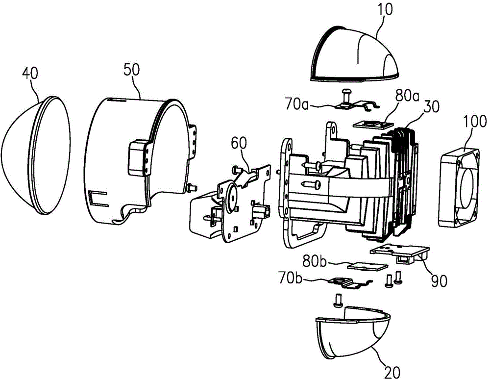
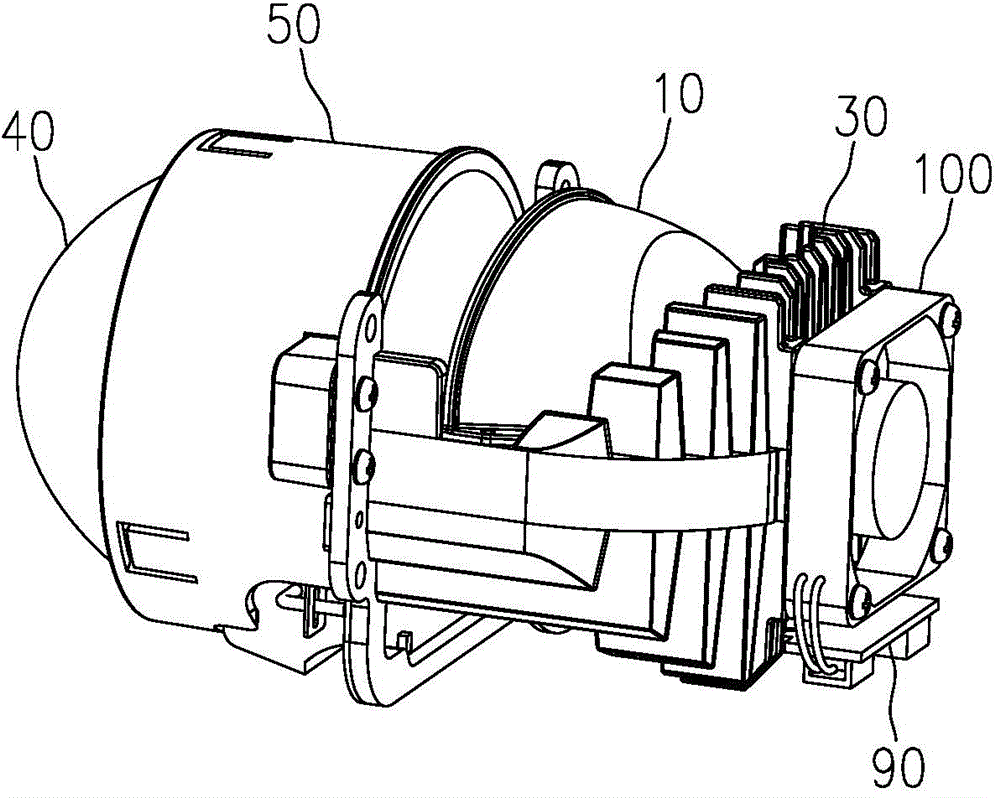
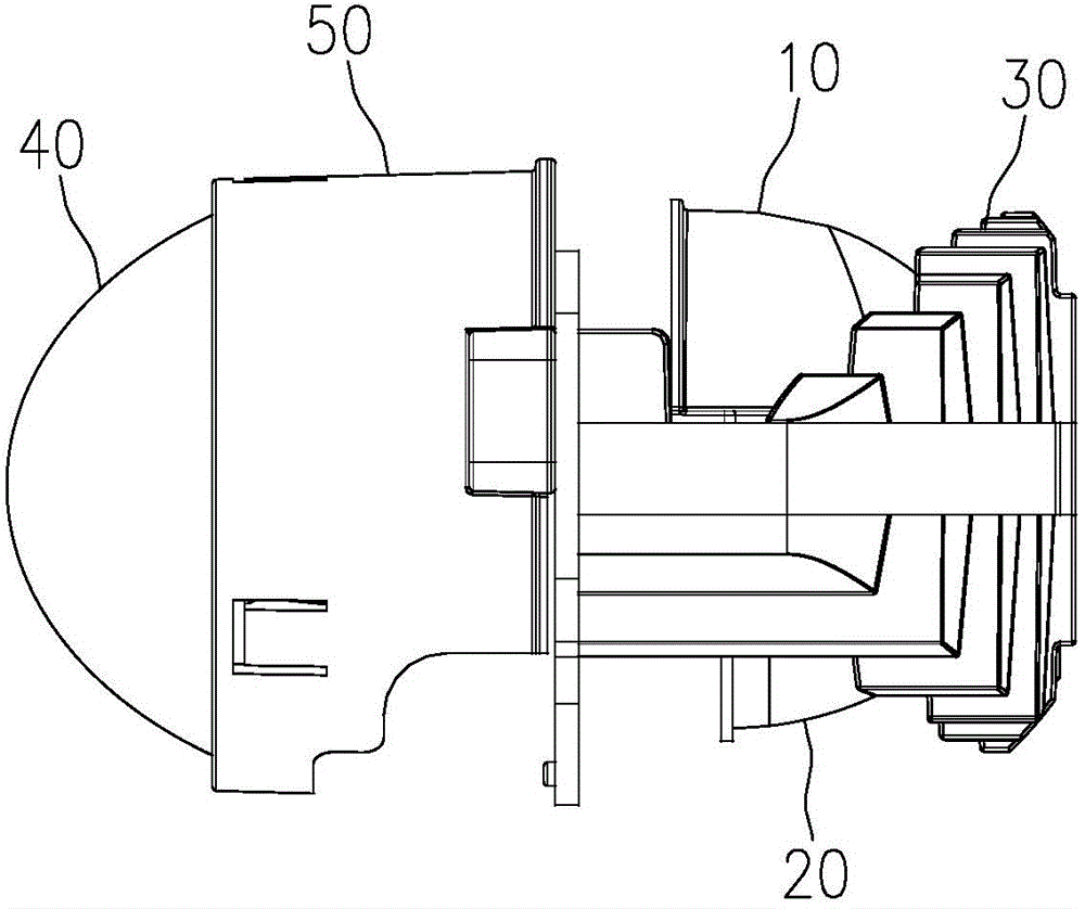
[0064] For ease of understanding, the specific structure of each component of the automobile headlamp module will be further described below in conjunction with the accompanying drawings.
[0065] 1. Lens
[0066] Such as Figure 5 , 6 As shown, the lens 40 is a plano-convex lens, including a planar incident surface 42 and a convex surface 41 for light to exit; the lens 40 is provided with a positioning convex ring 43 protruding outside the convex surface 41 on the side close to the incident surface 42 The rotation axes of the convex surface 41 and the positioning convex ring 43 coincide with each other; a transparent mirror is formed between the incident surface and the convex surface for light emission.
[0067] The lens 40 is made of high borosilicate optical grade glass.
[0068] Such as Image 6 As shown, the thickness of the convex surface 41 of the lens 40 is B, the front part with a thickness of B/3 from the top of the convex surface 41 to the side of the positioning convex ring 43 is an ellipsoidal surface, and the back part with a thickness of 2B/3 It is a parabola; the connection between the ellipsoid-shaped front part and the parabolic rear part has a smooth transition.
[0069] The light enters the parabolic rear section from the incident surface 42 first, and then the rear section converges the light entering it, and then the light enters the ellipsoidal front section, and the front section breaks up the light and emits it. The lens of the present invention distributes the incident light again and then emits it, so that the emitted light not only meets the national standard, but also can better satisfy the driving feeling of the passengers in the car.
[0070] 2. Sleeve
[0071] Such as Figure 7 , 8 As shown, the sleeve 50 is hollow. The sleeve 50 includes a circular cylindrical body and a fixing seat 52 arranged on the rear side of the cylindrical body. The cylindrical body and the fixing seat 52 are integrally formed. The inner side of the cylinder body is bent and has a ring-shaped limit flanging 51. The front cylinder wall of the cylinder body close to the limit flanging is provided with a claw part that cooperates with the limit flanging. The bottom part is provided with a notch 57 extending from the rear end of the cylinder to the front end of the cylinder.
[0072] Such as Figure 2~4 As shown, the notch 57 is provided at the right lower end of the sleeve 50, which facilitates timely heat dissipation.
[0073] Such as Figure 7 , 8 As shown, the claw portion includes three claws 53 evenly arranged on the wall of the front section of the cylinder along the circumferential direction. The rear end of the claws 53 is connected with the wall of the front section of the cylinder as a whole. The front end of the claw 53 is cantilevered forward along the cylinder axis, that is, a hollow portion 55 is provided between the front end of the claw 53 and the cylinder wall, and the claw 53 is gradually elastically biased toward the inside of the cylinder from its rear end to the front end. The front end of any claw 53 is provided with a limiting block 54 protruding toward the inside of the cylinder. The limiting block 54 is set as a slope toward the side of the fixing seat 52, and the limiting block 54 is between the limiting flange 51 Form a limit area.
[0074] Such as Figure 7 As shown, the end surface of the fixing seat 52 is provided with a process installation hole 56 and a fastening threaded hole.
[0075] 3. Upper reflector
[0076] Such as Figure 11~13 As shown, the upper reflector cup 10 includes an upper reflector cup body 11, the upper reflector cup body 11 is provided with an upper reflector cup reinforcement plate 12 on the side of the cup mouth, and the bottom of the upper reflector cup body 11 is provided with an outwardly protruding upper The reflector positioning plate 13, the upper reflector positioning plate 13 is provided with an upper reflector positioning hole 131; the surface of the upper reflector positioning plate 13 is horizontal, and the surface of the upper reflector reinforcement plate 12 is in line with the upper reflector. The plate surface of the cup positioning plate 13 is perpendicular to the vertical surface; the plane obtained by the intersection of the central axis of the upper reflector cup reinforcing plate 12 and the central axis of the upper reflector cup positioning plate 13 is the projection surface of the upper reflector cup. The positioning plate 13 is on the projection surface of the upper reflector (in the Picture 12 The middle is the projection length parallel to the paper surface direction or the paper surface direction) is greater than the projection length of the upper reflector cup reinforcing plate 12 on the upper reflector cup projection surface.
[0077] Such as Picture 12 , 13 As shown, the inside of the upper reflector cup body 11 is the upper reflector reflection surface 111, and the projection length of the upper reflector positioning plate 13 on the upper reflector projection surface is L1, which is close to the cup opening and has a length of 2L1/5 The upper reflector positioning plate is the front part of the upper reflector positioning plate, and the upper reflector positioning plate on the side away from the cup mouth and the length of L1/5 is the rear part of the upper reflector positioning plate, and the middle length is 2L1/5. The reflector positioning plate is the middle section of the upper reflector positioning plate. The upper reflector cup reflecting surface 111 is composed of a first upper reflector cup reflecting surface, a second upper reflector cup reflecting surface, and a third upper reflector cup reflecting surface that are sequentially connected. The first upper reflector cup reflecting surface and the upper reflector The front part of the cup positioning plate is correspondingly connected, the second upper reflecting cup reflecting surface is correspondingly connected with the middle part of the upper reflecting cup positioning plate, and the third upper reflecting cup reflecting surface is correspondingly connected with the rear part of the upper reflecting cup positioning plate. The first upper reflector reflector, the second upper reflector reflector, and the third upper reflector reflector are all curved surfaces fitted by quadratic Bezier curves. The first upper reflector reflector and the second upper reflector The junctions between the reflective surfaces of the cup and between the reflective surface of the second upper reflective cup and the reflective surface of the third upper reflective cup are smooth transitions, and the reflective surface of the first upper reflective cup, the reflective surface of the second upper reflective cup, and the third The radius of curvature of the reflecting surface of the upper reflector cup decreases successively.
[0078] Such as Picture 11 As shown, the upper reflector cup positioning plate 13 is provided in two pieces, and the two reflector cup positioning plates 13 are symmetrically arranged on both sides of the upper reflector cup body 11 along the central axis of the upper reflector cup body 11.
[0079] Since the upper reflector reflector 111 of the upper reflector 10 is a curved surface fitted by a quadratic Bezier curve, the upper reflector reflector 111 enables the light emitted by the lower lamp bead, the LED light source, to be collected and utilized to the greatest extent , The light efficiency is greatly improved (the common design is only 64%, while the design in the present invention makes the light efficiency reach 82.9%), that is, the upper reflector reflection surface 111 of the present invention not only has better light type, but also brightness Higher, under the premise of meeting the standards, it also ensures the safety of driving.
[0080] 4. Lower reflector
[0081] Such as Figure 14-16 As shown, the lower reflector cup 20 includes a lower reflector cup body 21. The lower reflector cup body 21 is provided with a lower reflector cup reinforcing plate 22 on the side of the cup mouth, and the bottom of the lower reflector cup body 22 is provided with a lower protruding outward The reflector positioning plate 23, the lower reflector positioning plate 23 is provided with a lower reflector positioning hole 232; the surface of the lower reflector positioning plate 23 is horizontal, and the surface of the lower reflector reinforcement plate 22 is in line with the lower reflector The plate surface of the cup positioning plate 23 is perpendicular to the vertical surface; the plane obtained by the intersection of the central axis of the lower reflector reinforcement plate 22 and the central axis of the lower reflector positioning plate 23 is the projection surface of the lower reflector. The positioning plate 23 is on the projection surface of the lower reflector (in the Figure 16 The middle is the projection length parallel to the paper surface or the paper surface direction) is greater than the projection length of the lower reflector reinforcement plate 22 on the projection surface of the lower reflector;
[0082] It should be pointed out that the lower reflector positioning plate 23 of the lower reflector 20 when in the working position is located on the upper side, such as figure 1 , 3 , 4 shown. Figure 14-16 The lower reflector 20 shown in the figure is for better description of its structure, and is not displayed according to the working position.
[0083] Such as Figure 4 As shown, the inside of the lower reflector cup body 22 is the lower reflector cup reflecting surface 222.
[0084] Such as Figure 16 As shown, the projection length of the lower reflector positioning plate 23 on the projection surface of the lower reflector is L2, and the lower reflector positioning plate with a length of L2/6 on the side close to the cup mouth is the front part of the lower reflector positioning plate, away from the cup mouth The lower reflector positioning plate with a length of L2/6 on one side is the rear section of the lower reflector positioning plate, and the lower reflector positioning plate with a middle length of 2L2/3 is the middle section of the lower reflector positioning plate. The reflecting surface of the lower reflector 222 is composed of a first lower reflector reflecting surface, a second lower reflector reflecting surface, and a third lower reflector reflecting surface that are connected in sequence. The first lower reflector reflecting surface and the lower reflector The front section of the cup positioning plate is correspondingly connected, the second lower reflector cup reflecting surface is correspondingly connected with the middle section of the lower reflector positioning plate, and the third lower reflector cup reflecting surface is correspondingly connected with the rear section of the lower reflector positioning plate. The reflecting surface of the first lower reflector, the reflecting surface of the second lower reflector, and the reflecting surface of the third lower reflector are all curved surfaces fitted by quadratic Bezier curves. The reflecting surface of the first lower reflector and the second lower reflector The junctions between the reflective surfaces of the cup and between the reflective surface of the second lower reflector and the reflective surface of the third lower reflector are smooth transitions, and the reflective surface of the first lower reflector, the reflective surface of the second lower reflector, and the third The radius of curvature of the reflecting surface of the lower reflector decreases in turn.
[0085] Such as Figure 22 As shown, the lower reflector cup positioning plate 23 is provided in two pieces, and the two reflector cup positioning plates 23 are symmetrically arranged on both sides of the lower reflector cup body 22 along the central axis of the lower reflector cup body 22.
[0086] Since the lower reflector reflecting surface 222 of the lower reflector 20 is a curved surface fitted by a quadratic Bezier curve, the lower reflector reflecting surface 222 enables the light emitted by the lower lamp beads, the LED light source, to be collected and utilized to the greatest extent , The light efficiency is greatly improved (the common design is only 64%, while the design in the present invention makes the light efficiency reach 82.9%), that is, the lower reflector reflecting surface 222 of the present invention not only has better light type, but also brightness Higher, under the premise of meeting the standards, it also ensures the safety of driving.
[0087] Such as image 3 , 4 As shown, the upper reflector positioning plate 13 is on the upper reflector projection surface that is the lower reflector projection surface (in Figure 16 The middle is the projection length L1 parallel to the paper surface direction or the paper surface direction) is greater than the projection length L2 of the lower reflector positioning plate 23 on the upper reflector projection surface, that is, the lower reflector projection surface.
[0088] 5. Radiator
[0089] The heat sink 30 in the present invention is integrally formed by die-casting aluminum alloy, which reduces the thermal resistance to the greatest extent and improves the heat dissipation efficiency.
[0090] Such as Picture 9 , 10 As shown, the radiator 30 is provided with a positioning platform 31 for placing LED light sources. The LED light sources include an upper LED light source 80a arranged on the upper table 31a of the positioning platform and a lower LED light source 80b arranged on the lower table 31b of the positioning platform. The upper LED light source 80a is fixed by the upper fixing elastic piece 70a, and the lower LED light source 80b is fixed by the lower fixing elastic piece 70b.
[0091] The upper and lower sides of the positioning platform 31 are respectively provided with an upper reflector positioning platform 32a for fixing the upper reflector 10 and a lower reflector positioning platform 32b for fixing the lower reflector 20, the upper reflector positioning platform 32a and the lower reflector The table surface of the cup positioning table 32b protrudes outside the table surface of the positioning platform 31. The upper reflector cup positioning table 32a and the lower reflector cup positioning table 32b are both arranged in a semicircular ring shape, and the opening side of the semicircular ring is set as the light emission direction.
[0092] The heat sink 30 is provided with a plurality of parallel fin-shaped heat sinks 35 outside the upper reflector cup positioning table 32a and the lower reflector cup positioning table 32b, and there are gaps between adjacent heat sinks 35. The extension direction of the fin-shaped heat sink 35 is perpendicular to the table surface of the positioning platform 31.
[0093] The fin height of the heat sink 35 gradually decreases from the middle of the positioning platform 31 to the two sides of the positioning platform 31, such as Picture 9 , 10 As shown, the size of the heat sink 35 located in the middle of the positioning platform 31 is relatively large, while the size of the heat sink 35 located on both sides of the positioning platform 31 is relatively small. This structure is beneficial to improve the efficiency of radiation heat dissipation and convection heat dissipation.
[0094] Such as image 3 , 4 As shown, the size between the upper and lower ends of the heat sink 35 in the middle of the positioning platform 31 is consistent with the distance between the top of the upper reflector cup 10 and the bottom of the lower reflector 20, that is, the heat sink in the middle of the positioning platform 31 The size between the upper and lower ends of 35 should be at least equal to the distance between the top of the upper reflector cup 10 and the bottom of the lower reflector cup 20, so that the best heat dissipation effect will be achieved.
[0095] Such as figure 1 , 2 As shown in 9, several sets of heat sinks 35 in the middle of the positioning platform 31 are provided with fan mounting holes 351 on the side away from the positioning platform 31. The fan 100 is installed and fixed on the back of the radiator 30 through the fan mounting holes 351 during operation.
[0096] Such as Picture 9 , 10 As shown, the positioning platform 31 is provided with a heat dissipation channel 34, and the heat dissipation channel 34 runs through the entire positioning platform 31 along the light emission direction, that is, the heat dissipation channel 34 is provided with openings at both ends of the positioning platform 31 along the light emission direction. The opening of the heat dissipation channel 34 on the side close to the radiator 30 is set toward the fan 100.
[0097] Such as Picture 10 As shown, the positioning platform 31 is provided with a vacancy on its front side along the light emission direction, and the opening of the heat dissipation channel 34 on the front side of the locating platform 31 is opened at the vacancy. The disposition of the vacant part helps to form convective heat transfer and improves the heat dissipation effect.
[0098] Such as Figure 1~4 As shown, the exhaust direction of the fan 100 in the present invention coincides with and is opposite to the direction of light emission. At this time, the exhaust direction of the fan 100 has a reflector with a large amount of heat. Under the suction action of the fan 100, the air Flowing from the side of the lens 40 to the side of the fan 100, the air entrains the hot air escaping from the gap between the sleeve 50 and the radiator 30 in the course of the flow, and the air flows through the upper reflector cup 10 and the lower reflector cup 20 The cup surface finally passes through the gap between the adjacent heat sinks and is discharged; at the same time, the fan 100 also sucks out the hot air inside the headlight module through the heat dissipation channel 34 and discharges it. Therefore, the fan in the present invention greatly enhances the air convection performance through its ingenious exhaust path design, and realizes an excellent convection heat dissipation capability.
[0099] Such as Picture 9 , 10 As shown, the front side of the positioning platform 31, that is, the side where the light exits, is provided with a butting plate 33. The butting plate 33 is in a U shape composed of two vertical plates and a horizontal horizontal plate; the butting plate 33 is on its vertical plate. The upper and lower ends of the upper and lower ends are respectively provided with module positioning holes 333, a sleeve positioning column 331 and a sleeve mounting hole 332 are provided between the two module positioning holes 333 of the same upright plate; the butt plate 33 is still standing on its two A light blocking mechanism positioning hole 334 is respectively provided on the plate, and two light blocking mechanism positioning posts 335 are provided on the horizontal horizontal plate.
[0100] The two light blocking mechanism positioning holes 334 and the two light blocking mechanism positioning posts 335 cooperate with each other to ensure the stability of the installation of the light blocking mechanism 60, thereby facilitating that the light blocking plate 63 in the light blocking mechanism 60 can reliably exert its light blocking effect. Features.
[0101] Such as figure 1 , 2 As shown, the positioning platform 31 is also provided with a power adapter plate 90 on the underside of the fan 100, and the front end of the power adapter plate 90 passes through the underside of the heat sink 35 and is fixed on the lower table 31b of the positioning platform 31 .
[0102] 6. Light blocking mechanism
[0103] Such as figure 1 , 17a As shown in ~18b, the present invention also includes a light blocking mechanism 60 arranged in front of the upper reflector cup 10 and the lower reflector cup 20 before the light exits. The light blocking mechanism 60 includes a positioning plate fixedly connected to the docking plate 33 of the radiator 30 61. The positioning plate 61 is provided with a light blocking plate 63 and a driving mechanism 62 that drives the light blocking plate 63 to move; the driving mechanism 62 drives the light blocking plate 63 to move and makes the light blocking plate 63 sealed in the upper reflector cup 10 and the lower reflector cup 20 At the cup opening of the headlight to make the headlight emit a low beam type or deviate from the cup openings of the upper reflector cup 10 and the lower reflector cup 20 to make the headlight emit high beam type.
[0104] Such as Figure 19 As shown, the light blocking plate 63 includes a rotating shaft hole 631 for facilitating the articulation of itself and the positioning plate 61; the light blocking plate 63 is provided with a light blocking arm 632 and a toggle arm 633 on the side of the rotating shaft hole 631, respectively. The light blocking arm 632 is used to form a cut-off line.
[0105] The light blocking arm 632 is plate-shaped, and the plate surface of the plate-shaped light blocking arm 632 is perpendicular to the light emission direction. The upper edge of the light blocking arm 632 is provided with a first straight edge 6321 on the side close to the rotation axis hole 631. A second straight side 6323 is provided on the side away from the rotation shaft hole 631. The first straight side 6321 and the second straight side 6323 are not parallel and are connected together by an upwardly convex arc-shaped side 6322. The highest point of the side 6322 protrudes above the first straight side 6321 and the second straight side 6323.
[0106] Such as Figure 17a , 17b As shown, when the first straight edge 6321 is in a horizontal state, the horizontal plane of the first straight edge 6321 is higher than the higher end of the second straight edge 6323, that is, the horizontal plane of the first straight edge 6321 is higher than the first straight edge 6321. The highest point of the two straight sides 6323.
[0107] The driving mechanism 62 drives the toggle arm 633 to move, and when the light blocking arm 632 rotates up and down around the rotation shaft hole 631, the first straight side 6321, the arc-shaped side 6322, and the second straight side 6323 all protrude on the positioning plate 61 The upper side of the board edge to make the headlight emit a low beam light type (such as Figure 18a , 18b ), or the first straight side 6321, the arc-shaped side 6322 and the second straight side 6323 are all blocked by the upper edge of the positioning plate 61 so that the headlight emits high beam type (such as Figure 17a , 17b ) Two position states.
[0108] Specifically, such as Figure 17a , 17b As shown, at this time, the first straight side 6321 of the light blocking arm 632 is horizontal, and the second straight side 6323 is blocked by the positioning plate 61. At this time, the first straight side 6321, the upper edge of the positioning plate 61 and two The mouth of the reflector cup together surrounds an area for light emission, and the headlight module emits a high beam type. Please refer to the high beam type diagram Figure 22 Shown.
[0109] Such as Figure 18a , 18b As shown, the second straight side 6323 of the light blocking arm 632 is horizontal at this time. At this time, the first straight side 6321, the arc-shaped side 6322, the second straight side 6323 and the cup openings of the two reflector cups Synthesize the area where the light is emitted, and the car headlights emit a low beam type. Please refer to the low beam type diagram Figure 21 Shown.
[0110] The light blocking arm 632 with the curved upper edge formed by the first straight side 6321, the arc-shaped side 6322 and the second straight side 6323 cooperates with each other to more accurately control the light type and make the emitted light conform to the set light type.
[0111] The toggle arm 633 is provided with a toggle hole 6331, the output end of the drive mechanism 62, that is, the end of the toggle shaft 621 extends into the toggle hole 6331, and the toggle shaft 621 of the drive mechanism 62 passes through the toggle hole. 6331 drives the light blocking arm 632 of the light blocking plate 63 to rotate up and down around the rotation axis hole 631, so that the headlight module emits a low beam type or a high beam type.
[0112] Such as Figure 17a-19 As shown, the side of the second straight side 6323 away from the rotation shaft hole 631 is provided with a limiting slot 6324, and the upper edge of the positioning plate 61 is provided with a limiting slot 6324 at a corresponding position. Block 611.
[0113] by Figure 21 with Figure 22 It can be seen that the light pattern emitted by the headlight module is not only uniform and beautiful, but the displayed data and shape are also ideal, which has significant advantages compared with the current headlight illumination data and shape. Specifically, the light type emitted by this headlight module, regardless of width, thickness, uniformity or visible illuminance, meets or exceeds the national standard requirements, and the cut-off line of light and dark is clear, and the driving feeling is safe and reliable.
[0114] There are multiple implementation modes for the driving mechanism, for example, an electromagnetic attraction can be used. For this electromagnetic induction drive, reference may be made to the prior art.
[0115] The structure and working process of the headlight module will be described in detail below in conjunction with the drawings.
[0116] Such as figure 1 As shown, the high-efficiency LED dual-chip far and near beam integrated automotive headlight module includes an upper reflector cup 10, a lower reflector cup 20, a radiator 30, a lens 40, a sleeve 50, a light blocking mechanism 60, and an upper fixed elastic sheet 70a , The lower fixed elastic piece 70b, the upper LED light source 80a, the lower LED light source 80b, the power adapter board 90 and the fan 100.
[0117] The optical system in the present invention includes an upper LED light source 80a, a lower LED light source 80b, an upper reflector 10, a lower reflector 20, a lens 40, and a light blocking mechanism 60. The function of the light blocking mechanism 60 is realized on the one hand More precise control of the light type, on the other hand, it is used to switch the far and near light types to meet the light type requirements of the headlight module.
[0118] When working, first press the upper fixed spring 70a (stainless steel tension springs can be used) to press the upper LED light source 80a on the upper table 31a of the radiator positioning platform 31, and the lower fixed spring 70b presses the lower LED light source 80b on the heat sink On the lower table 31b of the positioning platform 31, the bottoms of the upper LED light source 80a and the lower LED light source 80b are tightly attached to the positioning platform 31 of the heat sink 30, thereby ensuring that the upper LED light source 80a and the lower LED The position of the light source 80b will not move, on the other hand, it is also beneficial to improve the heat dissipation efficiency.
[0119] Then the upper reflector cup 10 and the lower reflector cup 20 are respectively placed on the radiator 30, that is, screws are used to pass through the upper reflector positioning hole 131 on the upper reflector positioning plate 13 and the upper surface 31a of the radiator positioning platform 31. The upper reflector 10 is tightly fixed on the upper table 31a of the radiator 30; similarly, screws are used to pass through the lower reflector positioning holes 131 and 131 on the lower reflector positioning plate 23. The corresponding mounting holes on the lower table 31b of the radiator positioning platform 31, so that the lower reflector cup 20 is tightly fixed on the lower table 31b of the radiator 30; and on the rear side of the radiator 30 away from the sleeve 50 The power adapter board 90 and the fan 100 are fixedly installed, and the light blocking mechanism 60 is installed on the front side of the radiator 30.
[0120] When installing the lens, the lens 40 enters from the opening on the side of the fixing seat 52 of the sleeve 50, and moves along the inner wall of the cylinder to the front end of the cylinder to the inclined surface of the stop block 54. The rear end of the lens 40 is along the stop block 54 The inclined surface continues to move forward and open the limit block 54 at the front end of the claw 53. Finally, the lens 40 enters the limit area between the limit block 54 and the limit flange 51. At this time, the front end of the claw 53 elastically returns to the original position , The lens 40 is tightly locked in the sleeve 50.
[0121] After the lens 40 is installed, the sleeve 50 is tightly fixed to the mating plate 33 of the heat sink 30 through the process installation hole 56 and the fastening screw hole on the fixing seat 52.
[0122] The upper LED light source 80a and the lower LED light source 80b are respectively connected to the power adapter board 90 through a cable, and the upper LED light source 80a, the lower LED light source 80b and the power adapter board 90 are turned on during operation, and the upper LED light source 80a and the lower LED light source 80b are connected. All are energized to emit light, and the light emitted by the upper LED light source 80a is reflected by the reflecting surface 111 of the upper reflector 10, while the light emitted by the lower LED light source 80b is reflected by the reflecting surface 211 of the lower reflector 20, that is, the upper LED light source 80a, the lower The light emitted by the LED light source 80b is first reflected by the upper and lower reflector cups, and the reflected light is projected out after a second optical refraction by the lens 40, and finally the light emitted by the upper LED light source 80a and the lower LED light source 80b is effectively superimposed Together, we can get the outgoing light with more ideal light type, higher brightness and light efficiency.
[0123] In addition, after the upper reflector cup 10 and the lower reflector cup 20 are fixed on the radiator 30, lenses of different sizes can be connected through different sleeves, and the entire car headlight can also be installed on different lights using different mounting brackets. Inside, the flexible structure can be more adapted to different car headlights.
[0124] In summary, the light type obtained by the optical system of the present invention, regardless of width, thickness, uniformity or visible illuminance, meets or exceeds the requirements of the national standard, and the cut-off line of light and dark is clear, and the driving feeling is safe and reliable. .
Login to view more PUM


Description & Claims & Application Information
We can also present the details of the Description, Claims and Application information to help users get a comprehensive understanding of the technical details of the patent, such as background art, summary of invention, brief description of drawings, description of embodiments, and other original content. On the other hand, users can also determine the specific scope of protection of the technology through the list of claims; as well as understand the changes in the life cycle of the technology with the presentation of the patent timeline. Login to view more.
Login to view more Similar technology patents
Illuminating pen
Owner:邢元龙
Light-emitting advertisement making ink
Owner:成都科达电子商务有限公司
Photovoltaic-based passive intelligent curtain control system
PendingCN107928360AAutomatically control the degree of closureGood lightBatteries circuit arrangementsCurtain accessoriesAutomatic controlElectric energy
Owner:XUCHANG UNIV
Method for manufacturing quartz plane mirror for anti-explosion lamp
InactiveCN102345827AGood lightHigh transparencyLighting applicationsOffice buildingPneumatic pressureMegasonic cleaning
Owner:刘松
Classification and recommendation of technical efficacy words
- Good light
- Improve light efficiency and brightness
Photovoltaic-based passive intelligent curtain control system
PendingCN107928360AAutomatically control the degree of closureGood lightBatteries circuit arrangementsCurtain accessoriesAutomatic controlElectric energy
Owner:XUCHANG UNIV
Light-emitting advertisement making ink
Owner:成都科达电子商务有限公司
Illuminating pen
Owner:邢元龙
Method for manufacturing quartz plane mirror for anti-explosion lamp
InactiveCN102345827AGood lightHigh transparencyLighting applicationsOffice buildingPneumatic pressureMegasonic cleaning
Owner:刘松
Ultraviolet LED chip, manufacturing method of ultraviolet LED chip and ultraviolet LED
PendingCN108110105AImprove light extraction efficiencyImprove light efficiency and brightnessSemiconductor devicesPhysicsSuperlattice
Owner:GUANGDONG UNIV OF TECH
LED lamp bead, illuminating lamp and manufacturing method of LED lamp bead
PendingCN113659059AImprove takeout rateImprove light efficiency and brightnessSemiconductor devicesPhysicsAdhesive glue
Owner:深圳市佑明光电有限公司
High light efficiency wide-angle LED lamp
InactiveCN101435560AImprove light efficiency and brightnessLess dark areas of lightingPoint-like light sourceProtective devices for lightingLamp shellEngineering
Owner:熊明生
Ultra-thin hot cathode fluorescent lamp of liquid crystal television
InactiveCN102143643AImprove light efficiency and brightnessReduce the number of lampsElectric lighting sourcesGas discharge lamp detailsLCD televisionLight source
Owner:陈友余