

Hydrogen risk control system and control method for small-power nuclear reactor containment
A nuclear reactor and risk control technology, applied in the control of nuclear reactions, reactors, power plant safety devices, etc., can solve the problems of deflagration or even explosion, unsuitable for small containment, slow hydrogen elimination rate of passive hydrogen catalytic recombiners, etc. The effect of the risk of incendiary explosion
- Summary
- Abstract
- Description
- Claims
- Application Information
AI Technical Summary
Problems solved by technology
Method used
Image

Examples
Embodiment 1
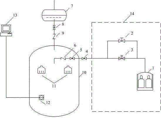
[0030] like figure 1 shown.
[0031] The low-power nuclear reactor containment hydrogen risk control system is characterized in that it includes a passive inert gas supply system and a steel containment system, and the steel containment system includes a steel pressure containment vessel 10, which is provided with The passive hydrogen removal device 11, the passive inert gas supply system includes an inert gas storage tank 1 communicating with the steel pressure containment vessel 10; the steel pressure containment vessel 10 is also connected with an exhaust system.
[0032] It can be seen from the above structure that during a serious accident of a low-power nuclear reactor, hydrogen gas will enter the steel pressure containment vessel after being generated, and accumulate in the steel pressure containment vessel. During this period, the concentration of hydrogen gas will gradually increase. It is very dangerous after reaching the explosion limit concentration, and the hydro...
Embodiment 2
[0034] On the basis of Example 1, in the specific implementation process of the present invention, the pipeline connecting the inert gas storage tank to the steel pressure containment vessel 10 is a passive gas supply pipeline, and the passive inert gas supply system also includes a manual cut-off The valve 2 and the pneumatic shut-off valve 3, and the manual shut-off valve 2 and the pneumatic shut-off valve 3 are arranged in parallel on the non-kinetic gas supply pipeline. The manual stop valve 2 and the pneumatic stop valve 3 are connected in parallel to form two types of switches. The pneumatic stop valve 3 is an automatic switch, and the manual stop valve 2 is a manual switch. After any of the manual stop valve 2 and the pneumatic stop valve 3 is opened, it can make The passive inert gas supply system injects inert gas into the steel pressure containment vessel to improve safety and prevent the system from being unable to operate after the pneumatic shut-off valve 3 fails. ...
Embodiment 3
[0036] On the basis of Example 2, preferably, the manual shut-off valve 2 and the pneumatic shut-off valve 3 and the inert gas storage tank are all set in the conventional island plant 14 . Pneumatic shut-off valve 3 is a shut-off valve powered by compressed air. When receiving a signal that needs to be opened, the pneumatic shut-off valve 3 can be opened automatically. When it cannot be opened for some reasons, the operator can open the system through the parallel manual shut-off valve.
PUM
 Abstract
Description
Claims
Application Information