A multi-frequency antenna device

A multi-frequency antenna and antenna technology, applied to antennas, devices that enable antennas to work in different bands at the same time, antenna coupling, etc., can solve the problems of separate identification of electronic signs, achieve increased electrical isolation, small size, and easy installation Effect

Active Publication Date: 2017-12-08
BEIJING HUAHANG HAIYING NEW TECH DEV +1
View PDF6 Cites 0 Cited by
  • Summary
  • Abstract
  • Description
  • Claims
  • Application Information

AI Technical Summary

Problems solved by technology

[0004] In view of the above analysis, the present invention aims to provide an antenna system capable of identifying three different frequency band electronic identifications at the same time, so as to solve the problem of separate identification of different frequency band electronic identifications in the prior art

Method used


Image

  • A multi-frequency antenna device
  • A multi-frequency antenna device
  • A multi-frequency antenna device

Examples


Embodiment Construction

[0026] Preferred embodiments of the present invention will be specifically described below in conjunction with the accompanying drawings, wherein the accompanying drawings constitute a part of the application and are used together with the embodiments of the present invention to explain the principles of the present invention.

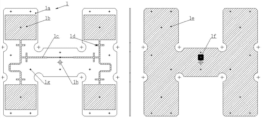
[0027] The embodiment of the present invention aims to provide a multi-frequency antenna device covering three electronic identification communication frequency bands of 800 / 900 MHz, 2.4 GHz and 5.8 GHz. The antenna can work at the same time or time-sharing, small in size, easy to install, and can flexibly meet the different index requirements of the system in different frequency bands for the antenna.

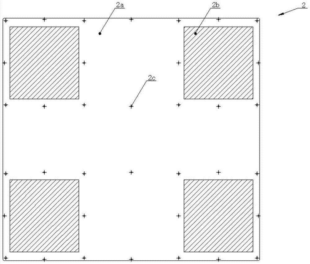
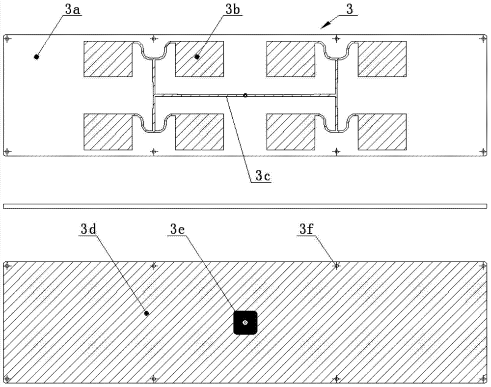
[0028] Antennas include PCB antenna 1 working in the 800 / 900MHz frequency band, PCB antenna 2 working in the 2.4GHz frequency band, PCB antenna 3 working in the 2.4GHz frequency band, PCB antenna 4 working in the 5.8GHz frequency band, and PCB antenna 5...


PUM


Abstract

The present invention relates to a multi-frequency antenna device, which includes a first printed board antenna, a second printed board antenna, a third printed board antenna, a fourth printed board antenna and a fifth printed board antenna, wherein The first printed board antenna and the second printed board antenna work in the first frequency band, the third printed board antenna works in the second frequency band, the fourth printed board antenna and the fifth printed board antenna work in the third frequency band, The radiating patch of the first printed board antenna and the radiating patch of the second printed board antenna have the same shape and the same location, and the patches of the first printed board antenna and the second printed board antenna are installed opposite to each other. The antenna device of the present invention can work at the same time or time-sharing, has small size, is easy to install, and can flexibly meet the different index requirements of the system on the antenna in different frequency bands.

Description

technical field [0001] The invention relates to antenna technology, in particular to an antenna device covering multiple operating frequency bands. Background technique [0002] In the transportation industry, in order to realize vehicle management and non-stop electronic toll collection, electronic signs with wireless communication capabilities will be installed on vehicles. Due to the fact that different vehicles are equipped with different electronic signs, and the same vehicle is equipped with multiple types of electronic signs, the identification and unified management of vehicle information become complicated. [0003] The communication frequency of electronic identification is mainly located in several fixed open frequency bands (800 / 900MHz, 2.4GHz, 5.8GHz), and each frequency band has a fixed standard narrowband channel. If the electronic identification system can work in the above-mentioned frequency bands at the same time, it can realize the comprehensive identifi...

Claims


Application Information

Patent Timeline
Patent Type & Authority Patents(China)
IPC IPC(8): H01Q1/38H01Q1/52H01Q5/50H01Q1/50H01Q13/08
Inventor 龚树军骆振龙
Owner BEIJING HUAHANG HAIYING NEW TECH DEV
Why Eureka
Try Eureka