Robot arm of endoscope manipulator and operation method thereof
A laparoscopic and arm technology, applied in the field of laparoscopic operating mobile phone arm and its operation, can solve the problems of affecting the viewing of the laparoscopic view, shaking the display screen, increasing the risk of surgery, etc., to solve the problem of holding the laparoscope, accurate positioning, and satisfying viewing effect of intention
- Summary
- Abstract
- Description
- Claims
- Application Information
AI Technical Summary
Problems solved by technology
Method used
Image
Examples
specific Embodiment 1
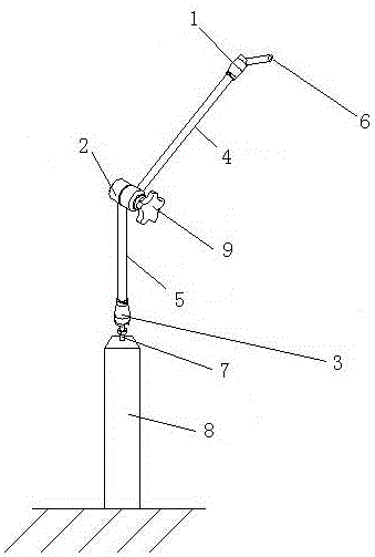
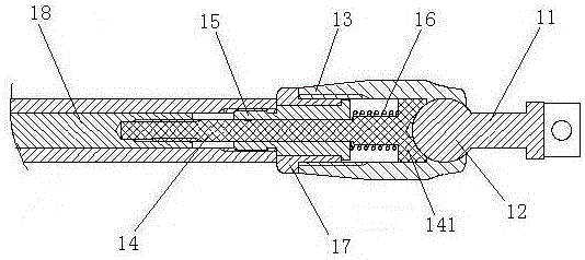
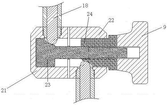
[0020] Such as figure 1 The robotic arm of the endoscopic operation handpiece shown includes two spherical joints, the front spherical joint 1 and the rear spherical joint 3, and a total of three joints, the middle joint 2; There are two connecting rods between the front connecting rod 4 and the rear connecting rod 5 connected between the middle joint 2 and the rear ball joint 3; the front ball joint 1 is connected with the laparoscopic operator through the connector 6; The rear spherical joint 3 is connected to the fixed seat 8 through the support rod 7; the front connecting rod 4 and the rear connecting rod 5 can rotate with the middle joint 2 as the center of rotation to adjust the spatial position of the two connecting rods; the laparoscopic operation The operable space of the mobile robot arm is the space between the two spherical surfaces, and the radius of the outer spherical surface is the sum of the distance from the front spherical joint 1 to the middle joint 2 and t...
specific Embodiment 2
[0029] The difference from Embodiment 1 is only that the knob 9 is fixedly connected with the upper oblique plug 23, and when the knob 9 rotates inwardly, the upper oblique plug 23 and the lower oblique plug 24 move toward each other and approach each other, and the upper oblique plug 23 and the lower oblique plug 23 The inclined plug 24 simultaneously extrudes the heads of the two ejector rods and stretches out the connecting rods, so that the ejector rod 18 drives the ejector rod 14 to move toward the ball head 12, and the two ejector rod heads 141 respectively press the respective corresponding The ball head 12 locks the two ball heads at the same time. At the same time, when the knob 9 rotates inwardly, it drives the upper support 21 close to the lower support 22, so that the lower support 22 contacts the upper support 21, so that the upper support The friction force between the lower support and the lower support is increased to lock the middle joint 2, and the three joint...
specific Embodiment 3
[0030] The difference with the specific embodiment 1 and the specific embodiment 2 is that: the upper support 21 and the lower support 22 are provided with an upper bevel groove and a lower bevel groove on the central axis of rotation of the hollow interior, when the two When the ball head is fully loosened, the ends of the two ejector rods extending into the support are completely located in the groove of the upper slope and the groove of the lower slope respectively. At the same time, the two supports are separated. At the same time, the three joints are in a loose state at the same time; one end of the central shaft is connected with a knob 9, and when the knob 9 rotates inward, the knob 9 and the rotating central shaft move toward each other, extruding the two ejector rods to extend out of the connecting rod The head of the ejector rod 18 drives the ejector rod 14 to move towards the direction of the ball head 12, and the two ejector rod heads 141 press the corresponding ba...
PUM
 Abstract
Description
Claims
Application Information
 - R&D
- Intellectual Property
- Life Sciences
- Materials
- Tech Scout
- Unparalleled Data Quality
- Higher Quality Content
- 60% Fewer Hallucinations
Browse by: Latest US Patents, China's latest patents, Technical Efficacy Thesaurus, Application Domain, Technology Topic, Popular Technical Reports.
© 2025 PatSnap. All rights reserved.Legal|Privacy policy|Modern Slavery Act Transparency Statement|Sitemap|About US| Contact US: help@patsnap.com


