Rotor type powder concentrator

A technology of powder separator and rotor type, which is applied in the direction of solid separation, separation of solids from solids by air flow, chemical instruments and methods, etc., which can solve the problems of reduced powder selection efficiency, reduced powder selection efficiency, and short service life of rotors, etc. problems, to achieve the effect of increased cement strength, reasonable particle size distribution, and increased output

Active Publication Date: 2015-10-21
弥勒羚羊能源有限公司
View PDF10 Cites 15 Cited by
  • Summary
  • Abstract
  • Description
  • Claims
  • Application Information

AI Technical Summary

Problems solved by technology

This principle will reduce the sorting efficiency to a certain extent, so that the efficiency of powder selection will be reduced.
[0004] At the same time, the fine powder particles are selected by the high speed of the rotor of the powder classifier. The high speed of the classifier results in a short service life of the rotor. At the same time, due to the space limitation between the guide blade and the rotor, the coarse powder particles cannot be effectively separated. The material and air cannot be mixed evenly, which reduces the efficiency of powder selection, increases the circulation of the cement tube mill, and causes overgrinding
[0005] Chinese patent application 201510070186.2 discloses a powder classifier, which adopts the method of bottom feeding, and disperses the material through a driving spreading disc to form a wind material mixture, but the wind material mixture formed in this way cannot It achieves full mixing of airflow and material, and the separation efficiency of the rotor is low, which cannot achieve a good separation effect

Method used


Image

  • Rotor type powder concentrator
  • Rotor type powder concentrator
  • Rotor type powder concentrator

Examples


Embodiment Construction

[0026] The present invention aims to provide a solution to achieve the purposes of improving powder selection efficiency, reducing over-grinding, making product particle size distribution more reasonable, and reducing system power consumption.

[0027] In order to achieve the above objective, the present invention adopts the following technical solutions.

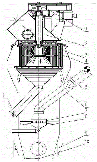
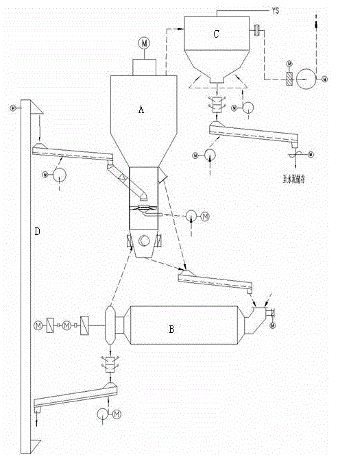
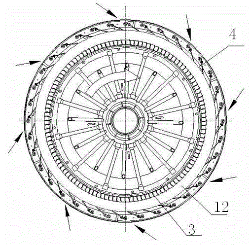
[0028] The high-efficiency rotor-type powder separator of the present invention includes a material dispersion device, a blowing device, an air compensation device, a rotor separation system, etc. The rotor separation system includes a sorting air chamber, a guide vane structure as a stator blade, and a rotor. After the airflow and materials are evenly mixed through the material dispersing device and the spraying device, they enter the stationary blade in the same rotation direction as the stationary blade. The material can be separated into coarse and fine particles in the sorting air chamber. Preferably, the guide blade struc...


PUM


Abstract

The invention discloses a rotor type powder concentrator. Bottom feeding is adopted in the powder concentrator, and materials entering the powder concentrator through a feeding device form an air mixture through a powder gas mixing system, wherein the powder gas mixing system comprises a powder dispersing device and a blowing device, and the blowing device is located on the periphery of the powder dispersing device and surrounds the powder dispersing device; an outlet of the feeding device is suspended above the powder dispersing device, wherein the blowing device is provided with a plurality of flow guide paddles, and the flow guide paddles are distributed on the periphery of the powder dispersing device and have the slant angles so that sprayed airflow can rotate in the powder concentrator; and the spirally-rising air material mixture is formed. By means of the rotor type powder concentrator, the yield is increased, the power consumption is reduced, and the product size distribution is more reasonable.

Description

Technical field [0001] The invention belongs to the technical field of cement sorting equipment in a cement closed-circuit grinding system, and specifically relates to a rotor-type powder separator with a redesigned structure in a cement closed-circuit grinding system. Background technique [0002] The classifier is widely used in the cement closed-circuit grinding system of cement plants, that is, to separate the coarse and fine powder from the cement tube mill export material, where the fine powder is sent to the cement storage facility as a finished product, and the coarse powder is returned to the cement tube mill Grind again. [0003] In the current closed-circuit cement grinding system, it is usually the classifier with the upper feeding system. The material is lifted to the top of the classifier through a hoist, and fed between the stator blade and the rotor of the powder classifier through the material spreader. After mixing between the moving blade and the rotor of the po...

Claims


Application Information

Patent Timeline
Patent Type & Authority Applications(China)
IPC IPC(8): B07B9/02B07B7/01B07B7/083B07B11/06
Inventor 李征龚汉保冯涛
Owner 弥勒羚羊能源有限公司
Why Eureka
Try Eureka