
Steam cleaning device for high-pressure oil pipe

A technology for cleaning devices and high-pressure oil pipes, applied in the field of cleaning machines, can solve problems such as low efficiency, oil pipes stained with oil, failures, etc., and achieve the effect of improving cleaning quality and high work efficiency

Active Publication Date: 2015-10-21
ZHANGJIAGANG CITY SHENGDINGYUAN PIPE MAKING
View PDF8 Cites 8 Cited by
  • Summary
  • Abstract
  • Description
  • Claims
  • Application Information

AI Technical Summary

Problems solved by technology

[0002] Automobile oil pipes are generally small-diameter high-pressure oil pipes. The oil pipes are often covered with oil, scale and iron oxides. After a long time, failures will occur. Therefore, the effect of oil pipe cleaning directly affects the oil supply effect. Therefore, how to improve the quality of oil pipe cleaning and efficiency have become a very hot topic in the tubing cleaning industry in recent years. In the traditional cleaning process, chemical agent cleaning, high-pressure water jet cleaning, and hot water boiling cleaning are common methods. Chemical agent cleaning is very serious for environmental pollution. High-pressure water Under low temperature conditions, it is difficult to clean heavy oil and greasy dirt with jet flow. Boiling in hot water is to put the oil pipe to be cleaned into a boiling water pool for cleaning. Susceptible to the secondary pollution of oil slick on the water surface, the cleaning effect is not ideal

Method used


Image

  • Steam cleaning device for high-pressure oil pipe
  • Steam cleaning device for high-pressure oil pipe
  • Steam cleaning device for high-pressure oil pipe

Examples


Embodiment Construction

[0019] The present invention will be further explained below in conjunction with the accompanying drawings and specific embodiments. It should be understood that the following specific embodiments are only used to illustrate the present invention and are not intended to limit the scope of the present invention. It should be noted that the words "front", "rear", "left", "right", "upper" and "lower" used in the following description refer to the directions in the drawings, and the words "inner" and "outer ” refer to directions towards or away from the geometric center of a particular part, respectively.

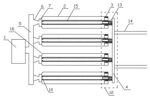
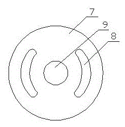
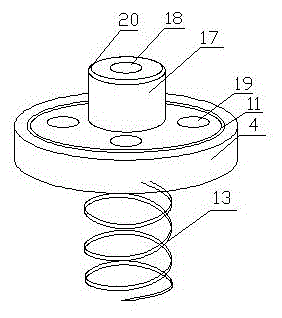
[0020] As shown in the figure, a high-pressure oil pipe steam cleaning device according to the present invention includes a high-pressure steam cleaning machine 1, a cleaning box 2, a sealing plate 3, and a limit plate 4. The cleaning box 2 is a hollow cylinder, and the The number of cleaning boxes 2 and sealing plates 3 is 3-8. The high-pressure steam cleaning machine 1 commun...


PUM


Abstract

The invention discloses a steam cleaning device for a high-pressure oil pipe. The steam cleaning device comprises a high-pressure steam cleaner, three to eight cleaning boxes, three to eight sealing plates and a limiting plate. The cleaning box is a hollow cylinder. The high-pressure steam cleaner is communicated with an air distribution chamber at the front end of each cleaning box through a pipeline air outlet. The cleaning boxes are communicated with the air separation chambers through vent holes outside the pipe and vent hole inside the pipe. Supporting pipes are arranged on the inner sides of the vent holes inside the pipe. The sealing plates are arranged at the rear ends of the cleaning boxes through circular grooves. Steam outlets are arranged on the sealing plates. A water collection box is arranged below the steam outlets. A spring is arranged at the rear end of each sealing plate. The limiting plate is arranged at the rear ends of the springs. The lower portion of the limiting plate is communicated with a track through a roller. The traditional cleaning technology is changed, and the inner and outer walls of the high-pressure oil pipe can be cleaned simultaneously at high temperature, so that the cleaning quality of the high-pressure oil pipe is improved; steam generates no other scales, so that no secondary pollution is generated; and a plurality of oil pipes can be cleaned at the same time, so that the working efficiency is high.

Description

technical field [0001] The invention belongs to the technical field of cleaning machines, and in particular relates to a high-pressure oil pipe steam cleaning device. Background technique [0002] Automobile oil pipes are generally small-diameter high-pressure oil pipes. The oil pipes are often covered with oil, scale and iron oxides. After a long time, failures will occur. Therefore, the effect of oil pipe cleaning directly affects the oil supply effect. Therefore, how to improve the quality of oil pipe cleaning and efficiency have become a very hot topic in the tubing cleaning industry in recent years. In the traditional cleaning process, chemical agent cleaning, high-pressure water jet cleaning, and hot water boiling cleaning are common methods. Chemical agent cleaning is very serious for environmental pollution. High-pressure water Under low temperature conditions, it is difficult to clean heavy oil and greasy dirt with jet flow. Boiling in hot water is to put the oi...

Claims


Application Information

Patent Timeline
IPC IPC(8): B08B9/023B08B9/032
CPCB08B9/023B08B9/032B08B9/0323B08B9/0327B08B2203/02
Inventor 陈惠明
Owner ZHANGJIAGANG CITY SHENGDINGYUAN PIPE MAKING
Learn More