Workpiece clamping fixture and winding reel welding machine using the clamping fixture

A winding reel and welding machine technology, which is applied in the direction of manufacturing tools, welding equipment, welding equipment, etc., can solve the problems of inaccurate positioning of workpieces, manual placement, etc., and achieve accurate and reliable actions, simple structure, and low failure rate. Effect

Active Publication Date: 2016-09-07
ZHENGZHOU RES INST OF MECHANICAL ENG CO LTD
View PDF6 Cites 1 Cited by
  • Summary
  • Abstract
  • Description
  • Claims
  • Application Information

AI Technical Summary

Problems solved by technology

[0005] The present invention provides a workpiece clamping fixture to solve the technical problem of inaccurate positioning of the workpiece caused by manual placement and clamping of the workpiece in the prior art; , the present invention also provides a winding reel welding machine using the above-mentioned workpiece clamping fixture

Method used


Image

  • Workpiece clamping fixture and winding reel welding machine using the clamping fixture
  • Workpiece clamping fixture and winding reel welding machine using the clamping fixture
  • Workpiece clamping fixture and winding reel welding machine using the clamping fixture

Examples


Embodiment Construction

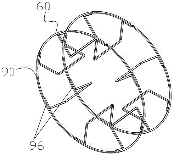
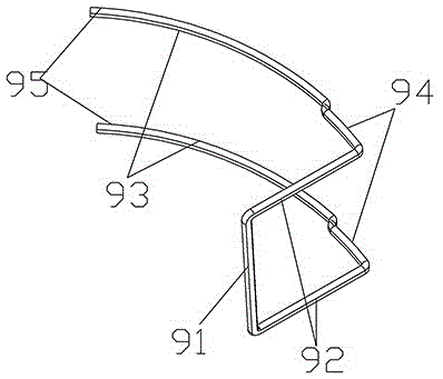
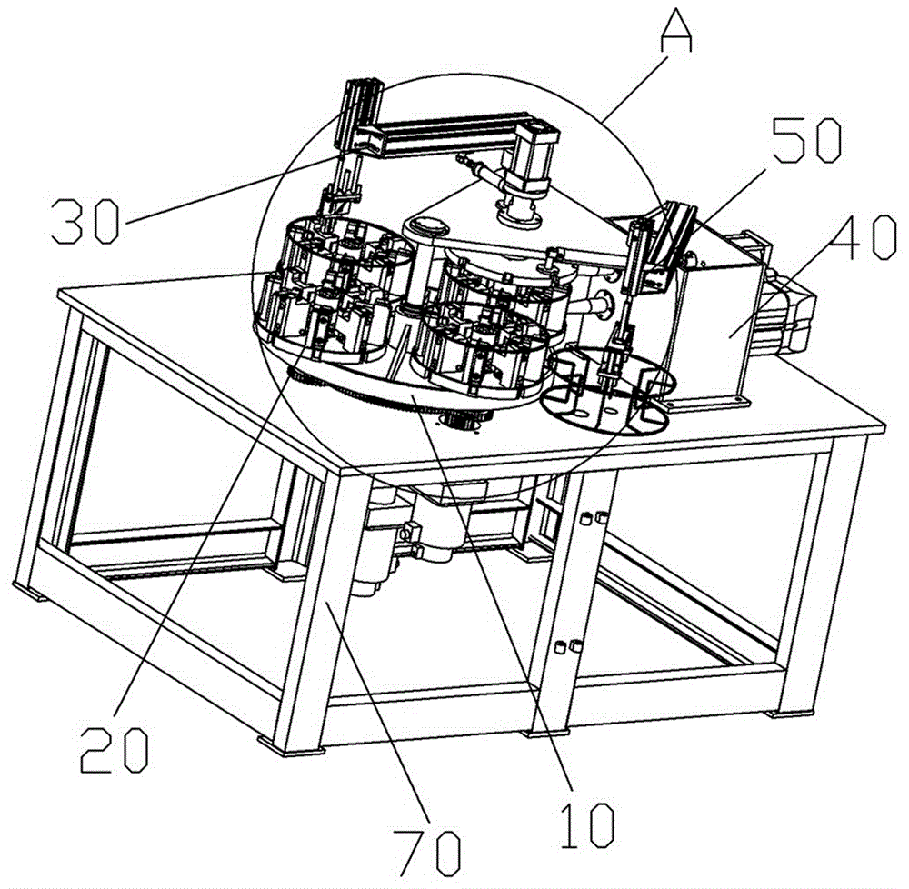
[0043] as shown in the picture 3 to picture 1 As shown in 8, an embodiment of a winding reel welding machine, the welding machine in this embodiment can be used for welding assembly as shown in the picture 1 , picture 2 Shown is a spool 60 for winding welding wire.

[0044] The welding machine provided in this embodiment includes a frame 70, on which a planetary gear train transmission mechanism 100, a clamping fixture 20 for clamping each component unit 90 of the winding reel, and an upper part for loading the component unit 96 are arranged on the frame 70. Material device 30, welding device 40, and feeding device 50.

[0045] The welding machine provided in this embodiment drives the clamping fixture through four stations successively through the planetary gear transmission mechanism 100, which are respectively the preparation station, the loading station, the welding station and the blanking station. The positions are evenly distributed along the circumferential...


PUM


Abstract

The invention provides a workpiece clamping fixture and a winding reel welding machine using the clamping fixture. The welding machine includes a clamping fixture. The positioning seat of the clamping fixture is provided with a circular reference plane. Each clamping component can move back and forth along the radial direction of the circumference, and the clamping block of each clamping component is driven by the clamping drive mechanism to close when each clamping component moves close to the corresponding circumferential reference plane to clamp the component The unit is opened when each clamping component moves away from the corresponding circumferential reference plane. Each clamping component has a fixed station on the reciprocating movement stroke. When each clamping component moves to the fixed station, the arc shape of each component unit The top is pressed against the circumferential datum plane. While the clamping component clamps and fixes the constituent units, the clamping component that moves close to the circumferential reference plane also directly presses and fixes the arc-shaped part of the constituent units on the circumferential reference plane, finally ensuring the automatic and accurate positioning of each constituent unit .

Description

technical field [0001] The invention relates to a workpiece clamping fixture and a wire coil welding machine using the clamping fixture. Background technique [0002] Welding is a commonly used fixed connection method in the mechanical field. Most welding processes require the use of welding wire. During welding, the welding wire and the workpiece need to be melted at high temperature, and a fixed connection is formed after cooling. In the process of welding wire production, welding wire packaging and welding wire use, the winding reel is required. When in use, the welding wire is wound in layers in the groove in the middle of the winding reel. Commonly used winding reels are mostly made by injection molding, which has many consumables, high cost, and is prone to breakage, which affects the normal support of the welding wire. [0003] In the Chinese utility model patent specification whose authorized announcement number is CN201128645Y, a kind of such as figure 1 The shown...

Claims


Application Information

Patent Timeline
Patent Type & Authority Patents(China)
IPC IPC(8): B23K37/04B23K11/02B23K11/36
CPCB23K11/002B23K11/02B23K11/36B23K37/0435
Inventor 李五田张亚强刘伟高建立
Owner ZHENGZHOU RES INST OF MECHANICAL ENG CO LTD
Why Eureka
Try Eureka