Laser marking method of coil spring

A laser marking method and helical spring technology, which are applied in laser welding equipment, metal processing equipment, welding equipment, etc., can solve the problems of not being able to see the logo clearly, low efficiency, and not being environmentally friendly, so as to achieve not easy to fall off, improve efficiency, The effect of neat and standardized color code

Active Publication Date: 2022-01-04
SHANGHAI SPRING CORP
View PDF12 Cites 0 Cited by
  • Summary
  • Abstract
  • Description
  • Claims
  • Application Information

AI Technical Summary

Problems solved by technology

This method is not only inefficient and error-prone, but also not environmentally friendly. After the spring is assembled, the paint may fall off, causing the staff to be unable to see the logo clearly.

Method used


Image

  • Laser marking method of coil spring
  • Laser marking method of coil spring
  • Laser marking method of coil spring

Examples


Embodiment Construction

[0015] The present invention will be further described below in conjunction with the accompanying drawings.

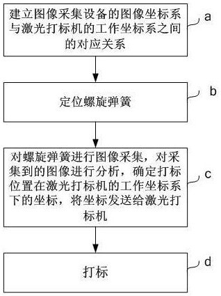
[0016] Please refer to figure 1 . A laser marking method for a helical spring according to an embodiment of the present invention comprises the following steps;

[0017] a. Through calibration, establish the corresponding relationship between the image coordinate system of the image acquisition device and the working coordinate system of the laser marking machine;

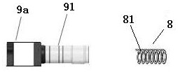
[0018] b. Positioning the helical spring. The end coil of the helical spring to be marked is facing the lens of the image acquisition device; in a specific embodiment, the helical spring can be positioned at a predetermined position by a positioning tool. The positioning datum of all coil springs to be marked is the same. figure 2 A schematic diagram showing the positional relationship between the image acquisition device and the coil spring, from figure 2 It can be seen that the lens 91 of the image ...


PUM


Abstract

A laser marking method for a helical spring, comprising the following steps: a, through calibration, establish the corresponding relationship between the image coordinate system of the image acquisition device and the working coordinate system of the laser marking machine; b, positioning the helical spring, the helical spring The end ring to be marked is facing the lens of the image acquisition device; c. The image acquisition device collects the image of the coil spring, analyzes the collected image, determines the coordinates of the marking position in the image coordinate system, and according to the image The corresponding relationship between the coordinate system and the working coordinate system, determine the coordinates of the marking position in the working coordinate system of the laser marking machine, and send the coordinates to the laser marking machine; d, the laser marking machine according to the marking position in The coordinates under the working coordinate system of the laser marking machine print the marking pattern on the surface of the coil spring. The invention has high marking efficiency and good environmental protection, and can ensure that the marking positions of different springs have good consistency.

Description

technical field [0001] The invention relates to a laser marking method for springs. Background technique [0002] At present, the identification of coil springs is mainly realized by manually brushing paint on the surface of the springs. This method is not only inefficient and error-prone, but also not environmentally friendly. After the spring is assembled, the paint may fall off, causing the staff to be unable to see the logo clearly. Contents of the invention [0003] The technical problem to be solved by the present invention is to provide a laser marking method for coil springs, which not only has high marking efficiency and good environmental protection, but also can ensure good consistency of marking positions of different springs. [0004] The technical solution adopted in the present invention is: a laser marking method for a helical spring, comprising the following steps; [0005] a. Through calibration, establish the corresponding relationship between the imag...

Claims


Application Information

Patent Timeline
Patent Type & Authority Patents(China)
IPC IPC(8): B23K26/362B23K26/70
CPCB23K26/362B23K26/702
Inventor 周凯
Owner SHANGHAI SPRING CORP
Why Eureka
Try Eureka