Double-R supporting structure of injection molding machine

A technology of support structure and injection molding machine, applied in the field of support structure of injection molding machine, can solve the problems of increased wear of the support device and the rail surface of the rack, affecting the quality of plastic parts in the mold clamping state, and inability to compensate for the bending deformation of the fixed template. The effect of uniform force, simple structure and easy realization

Active Publication Date: 2015-10-21
SUZHOU UNIV
View PDF2 Cites 2 Cited by
  • Summary
  • Abstract
  • Description
  • Claims
  • Application Information

AI Technical Summary

Problems solved by technology

The support structure of the movable template and the fixed template of the existing injection molding machine are all arranged on the lower side of the template, although the forward tilt of the template can be prevented to a certain extent, but the bending deformation of the template under the action of the clamping force is inevitable
[0007] The support parts of the traditional general support structure are completely arranged on the lower side of the mobile formwork. When the heavy mold is installed on the mobile formwork, the mobile formwork tends to lean forward during the movement process. On the other hand, the forward tilt makes the holes of the Golin pillars on the mobile formwork deviate from the centers of the four Golin pillars, which accelerates the wear of the Golin pillars
In addition, the supporting parts cannot compensate the bending deformation of the fixed template caused by the clamping force, which in turn affects the clamping state of the mold and the quality of the plastic parts

Method used


Image

  • Double-R supporting structure of injection molding machine
  • Double-R supporting structure of injection molding machine
  • Double-R supporting structure of injection molding machine

Examples


Embodiment

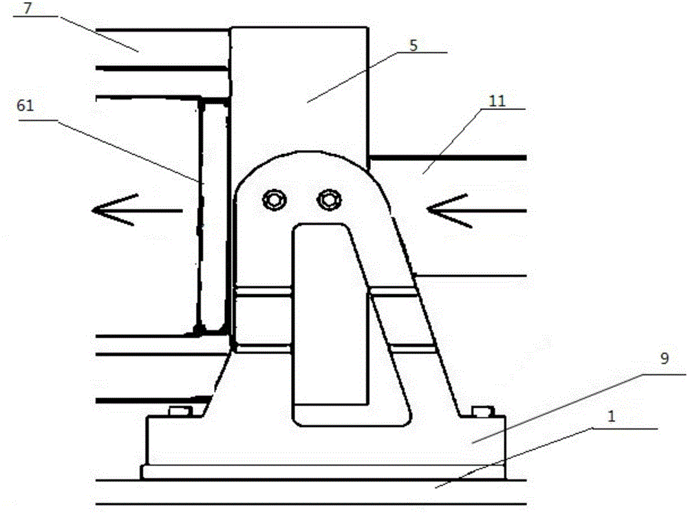
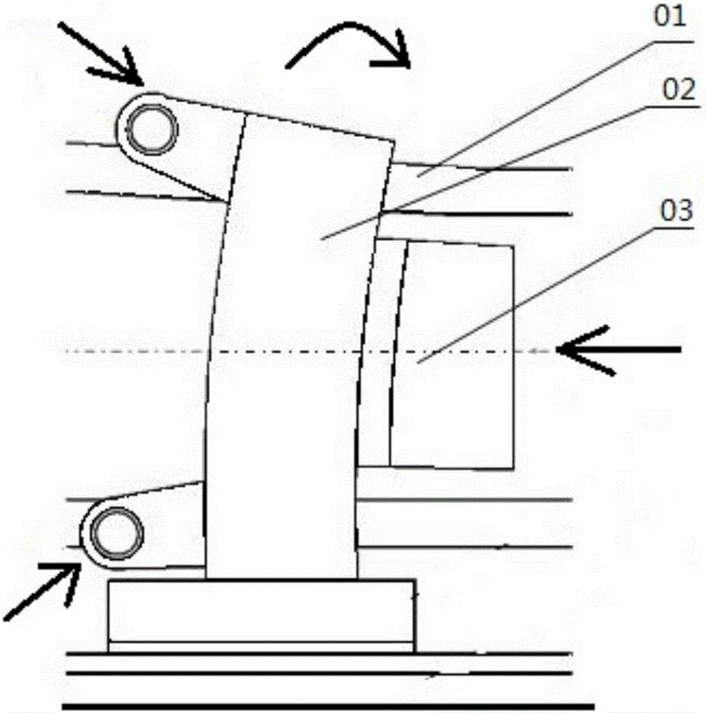
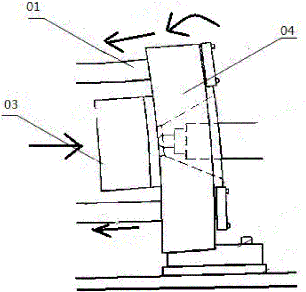
[0035] Embodiment: A double R support structure for an injection molding machine, including a base 1, two linear guide rails 2, several sliders 3, a moving template 4, a fixed template 5, a mold 6, and four Corinthian pillars 7 , one end of the Corinthian column is positioned on the fixed formwork, the other end passes through the mobile formwork, the mobile formwork can move on the Corinthian column, and the mold is installed on the mobile formwork and the fixed formwork Between the templates, the linear guide rail is fixed on the base, the slider is slidably positioned on the linear guide rail, and a reverse R-shaped support block 8 is respectively fixed on both sides of the mobile template symmetrically. A positive R-shaped support block 9 is fixed symmetrically to each other on both sides of the formwork, the reverse R-shaped support block is reverse R-shaped, the positive R-shaped support block is positive R-shaped, and the bottom of the reverse R-shaped support block is f...


PUM

PropertyMeasurementUnit
thicknessaaaaaaaaaa

Abstract

The invention discloses a double-R supporting structure of an injection molding machine. The double-R supporting structure comprises a base, two linear guide rails, a plurality of sliding blocks, a movable die plate, a fixed die plate, a die and four tie bars. One end of each tie bar is positioned on the fixed die plate, and the other end of each tie bar penetrates the movable die plate; the movable die plate can move on the tie bars, and the die is mounted between the movable die plate and the fixed die plate; the linear guide rails are fixed to the base, and the sliding blocks are positioned on the linear guide rails in a sliding manner; the two sides of the movable die plate are symmetric, and are each fixedly provided with a reverse-R-shaped supporting block; the two sides of the fixed die plate are symmetrically and fixedly provided with a positive-R-shaped supporting block; the bottoms of the reverse-R-shaped supporting blocks are fixed to the sliding blocks, and the sliding blocks are connected with the linear guide rails and can side on the guide rails; the bottoms of the positive-R-shaped supporting blocks are fixed to the base; and the double-R supporting structure of the injection molding machine can effectively prevent stress deformation of the fixed die plate and the movable die plate, the injection precision is improved, the production efficiency is improved, and the service life is prolonged.

Description

technical field [0001] The invention relates to a support structure of an injection molding machine, in particular to a double-R support structure of an injection molding machine. Background technique [0002] Injection molding plays an important role in plastic molding processing, and injection molding machine is the main equipment for completing injection molding. Among them, the clamping mechanism is an important part of the injection molding machine. The template is an important part in the mold clamping mechanism, and occupies a pivotal position in the injection molding machine. The template has the functions of fixing the mold and serving as a reference for the motion-guiding parts. It is a key component to achieve good locking and opening of the mold. The performance of the template is very large To a certain extent, it affects the quality of injection molded products. [0003] The mobile template is an important part for installing the mold and setting the ejector ...

Claims


Application Information

Patent Timeline
Patent Type & Authority Applications(China)
IPC IPC(8): B29C45/17
CPCB29C45/1742
Inventor 王传洋姜宁陈再良
Owner SUZHOU UNIV
Why Eureka
Try Eureka