Inner annular backoff demoulding mechanism for injection mould cavity piece

A technology of demoulding mechanism and inner ring, which is applied in the field of inner ring undercut ejection mechanism of injection mold cavity parts, which can solve the problems of low product yield, small width of inner ring undercut, easy deformation, etc.

Active Publication Date: 2015-10-21
ZHEJIANG KAIHUA MOLDS
View PDF5 Cites 8 Cited by
  • Summary
  • Abstract
  • Description
  • Claims
  • Application Information

AI Technical Summary

Problems solved by technology

[0002] In the injection mold, if the plastic part is circular, one side of the circular plastic part is formed with a wall, and the other side is an opening, and the inner wall of the opening is formed with an inner annular undercut structure. Make an inner annular undercut with a narrow width, and then force the ...

Method used


Image

  • Inner annular backoff demoulding mechanism for injection mould cavity piece
  • Inner annular backoff demoulding mechanism for injection mould cavity piece
  • Inner annular backoff demoulding mechanism for injection mould cavity piece

Examples


Embodiment Construction

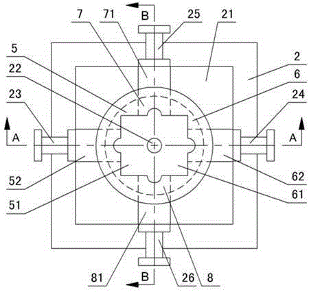
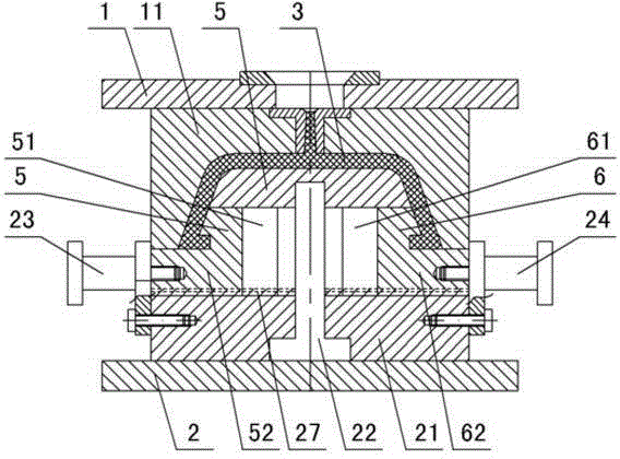
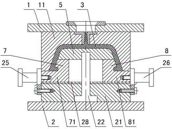
[0015] The invention relates to a ring-shaped undercut stripping mechanism in an injection mold cavity body, such as figure 1 — Figure 9 As shown, it includes an upper doubler plate 1 and a lower doubler plate 2, a cavity 11 is set under the upper doubler plate, a sliding seat 21 is set on the lower doubler plate, a core is set on the sliding seat, and there is an injection molding between the core and the cavity. The plastic part 3 is formed with an inner annular undercut 31 under the plastic part. It is characterized in that: the support column 22 is set in the slide seat 21, and the left oil cylinder 23, the right oil cylinder 24, the front oil cylinder 25 and the outer side of the slide seat 21 are installed. Rear oil cylinder 26, sliding seat 21 is shaped on left and right slide rails 27 and front and rear slide rails 28, and described mold core comprises the main mold core 4 of top, is provided with left inner core pulling 5, right inner core pulling 6, The front inner...


PUM


Abstract

An inner annular backoff demoulding mechanism of an injection mould cavity piece comprises an upper compound plate and a lower compound plate, wherein a cavity is formed in the upper compound plate; a sliding seat is arranged on the lower compound plate; a core is arranged on the sliding seat; a plastic piece is arranged between the core and the cavity; and an inner annular backoff is arranged below the plastic piece. The inner annular backoff demoulding mechanism is characterized in that a support pillar is arranged in the sliding seat; a left oil cylinder, a right oil cylinder, a front oil cylinder and a rear oil cylinder are mounted on the outer side of the sliding seat; a left and right sliding rail and a front and rear sliding rail are formed in the sliding seat; the core comprises a main core and a left inner loose core, a right inner loose core, a front inner loose core and a rear inner loose core which are arranged under the main core; the main core is connected with the support pillar; the left, right, front and rear inner loose cores are matched with the inner annular backoff in the plastic piece; a left groove is formed in the left inner loose core; a left sliding block is arranged below the left inner loose core; the left oil cylinder drives the left sliding block to slide on the left and right sliding rail; a right groove is formed in the right inner loose core; a right sliding block is arranged below the right inner loose core; the right oil cylinder drives the right sliding block to slide on the left and right sliding rail; a front sliding block is arranged below the front inner loose core; the front oil cylinder drives the front sliding block to slide on the front and rear sliding rail; a rear sliding block is arranged below the rear inner loose core; and the rear oil cylinder drives the rear sliding block to slide on the front and rear sliding rail.

Description

technical field [0001] The invention relates to an injection mold, in particular to a ring-shaped undercut ejection mechanism in a cavity body part of an injection mold. Background technique [0002] In the injection mold, if the plastic part is circular, one side of the circular plastic part is formed with a wall, and the other side is an opening, and the inner wall of the opening is formed with an inner annular undercut structure. Make an inner annular undercut with a narrow width, and then force the inner annular undercut of the plastic part out of the core, so that the plastic part is easily deformed or even broken when it is demoulded at the undercut, and the product yield rate Low, thereby increasing the production cost, and the width of the inner ring undercut is small, the assembly is unreliable, and the use effect is affected. Contents of the invention [0003] The purpose of the present invention is to overcome the shortcomings of the prior art, to provide a mol...

Claims


Application Information

Patent Timeline
IPC IPC(8): B29C45/33B29C45/40
CPCB29C45/33B29C45/40
Inventor 梁正华
Owner ZHEJIANG KAIHUA MOLDS
Why Eureka
Try Eureka