Pull-type full-automatic sun protection device for solar vehicle
A solar car, fully automatic technology, applied in vehicle components, transportation and packaging, removable outer sheaths, etc., can solve the lack of feasibility, not considering the deployment mechanism, unable to close the sunshade to the window and windshield, etc. problems, to achieve the effect of improving adaptability and reliability, good heat dissipation, and good sun protection.
- Summary
- Abstract
- Description
- Claims
- Application Information
AI Technical Summary
Problems solved by technology
Method used
Image

Examples
Embodiment Construction
[0036] The present invention will be further described in detail below in conjunction with the accompanying drawings and specific embodiments.
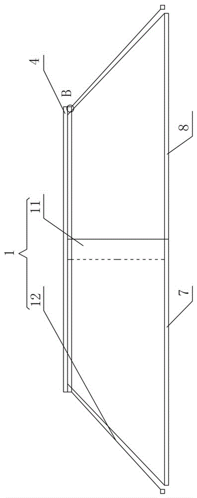
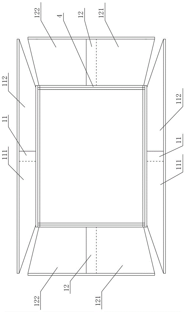
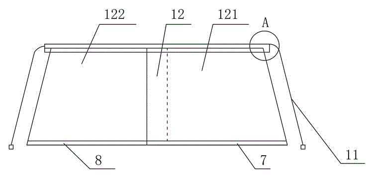
[0037] Figure 1 to Figure 17 It shows an embodiment of the pull-type automatic sun protection equipment for solar vehicles of the present invention, the sun protection equipment includes a sun protection clothing 1, a solar photovoltaic panel 2, a storage battery 3 and a heat-insulating retractable shelf 4, and the sun protection clothing 1 includes and The sun-proof side clothing 11 and the sun-proof top clothing 12 fitted with the car windshield, the sun-proof side clothing 11 and the sun-proof top clothing 12 are all movably connected with the heat insulation retractable layer frame 4, and the sun-proof side clothing 11 includes Two trapezoidal front side garments 111 and rear side garments 112, sun protection top garment 12 comprise two trapezoidal left top garments 121 and right top garment 122, heat insulation retractable shelf...
PUM
 Abstract
Description
Claims
Application Information
PatSnap Eureka turns technology decisions into work you can execute. Powered by our Innovation Knowledge Graph, it runs expert workflows across engineering, life sciences, materials and intellectual property. Get your review-ready output in minutes.


