Drive motor stall frequency control method and device

A technology for driving motors and control methods, which can be applied in control driving, electric vehicles, electric energy management, etc. It can solve problems such as vehicle vibration and distortion of torque command values, solve temperature rise problems, ensure load requirements, and ensure safety and comfort sexual effect

Active Publication Date: 2017-05-10
ANHUI JIANGHUAI AUTOMOBILE GRP CORP LTD
View PDF6 Cites 0 Cited by
  • Summary
  • Abstract
  • Description
  • Claims
  • Application Information

AI Technical Summary

Problems solved by technology

This kind of jitter cannot cause the whole vehicle to jitter in a very short time, but if the electric vehicle is always in the critical working condition of locked rotor and non-locked rotor, the switching frequency is constantly switched, and the torque command value is distorted due to the distortion of the rotational speed. If the time is too long, it will cause the vehicle to vibrate

Method used


Image

  • Drive motor stall frequency control method and device
  • Drive motor stall frequency control method and device
  • Drive motor stall frequency control method and device

Examples


Embodiment Construction

[0052] Below in conjunction with accompanying drawing and specific embodiment the present invention is described in further detail:

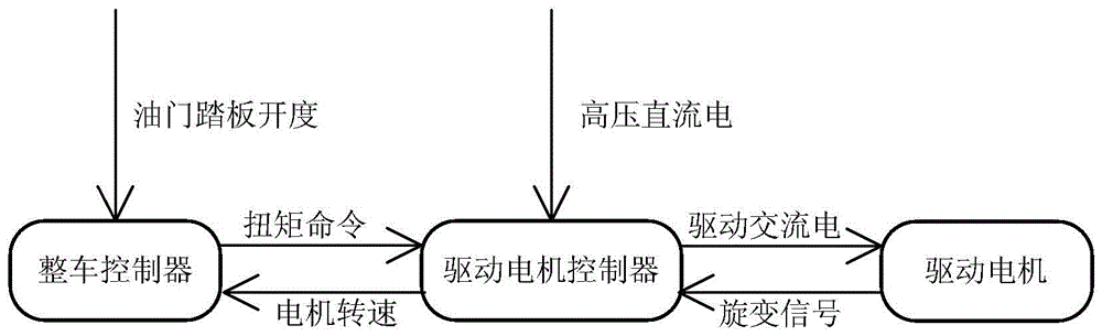
[0053] The working principle of the drive system of electric vehicles can be briefly as follows: figure 1As shown, the vehicle controller sets the torque according to the accelerator pedal opening and the motor speed signal. After the drive motor controller receives the torque command, it controls the drive motor to output the corresponding torque when the drive system is not faulty. The first step is to obtain a set of Id and Iq by looking up the torque value at the current rotational speed (the relationship table between motor torque and current), and then through the space vector algorithm, the controller U, V, W three-phase current.

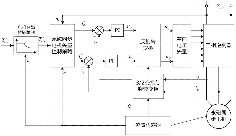
[0054] figure 2 Basic block diagram of vector control for drive motor controller. Firstly, the drive motor controller obtains the torque value that the motor can actually send out according to the torque rec...


PUM


Abstract

The invention discloses a locked rotor frequency conversion control method and device for drive motors. By means of the locked rotor frequency conversion control method and device, entry and exit of locked rotor frequency conversion are judged through the locked rotor rotating speed zone bit and the locked rotor torque zone bit, and therefore the temperature rise problem of a drive controller in the blocked rotor process is effectively solved. Thus, the time spent when a drive motor outputs large torque is prolonged as much as possible, and the load requirement is guaranteed. Meanwhile, the entry time and the exit time of locked rotor frequency conversion are staggered, the vehicle shaking problem under the critical working condition is solved, and driving safety and comfort are ensured.

Description

technical field [0001] The invention belongs to the field of electric vehicle drive motor control, in particular to a drive motor blocking frequency control method and device Background technique [0002] The development and application of electric vehicle drive stall frequency technology solves the IGBT (Insulated Gate Bipolar Transistor, insulated gate bipolar transistor) over-temperature protection when the drive motor controller is in stall, thus avoiding the IGBT over-temperature protection caused by A series of security risks. Usually the IGBT switching frequency in the drive motor controller is 10K. The vehicle controller sends a torque command to the drive motor controller according to the accelerator pedal signal and the vehicle speed signal (obtained from the conversion of the motor speed). When the rotor is locked, the driver will increase the throttle, the torque command received by the drive motor controller will increase, and the current of the IGBT will also...

Claims


Application Information

Patent Timeline
Patent Type & Authority Patents(China)
IPC IPC(8): B60L15/20
CPCY02T10/72
Inventor 艾敬尧肖梦郭航程胜民
Owner ANHUI JIANGHUAI AUTOMOBILE GRP CORP LTD
Why Eureka
Try Eureka