
Front clamping jaw conveying mechanism for automatic sheet conveying mechanism

A technology of automatic feeding and conveying mechanism, applied in the direction of conveyor objects, transportation and packaging, furnaces, etc., can solve the problems of clamping devices without sheet materials, etc., and achieve the effect of firm clamping and good clamping effect

Active Publication Date: 2015-10-21
BOZHON PRECISION IND TECH CO LTD
View PDF6 Cites 4 Cited by
  • Summary
  • Abstract
  • Description
  • Claims
  • Application Information

AI Technical Summary

Problems solved by technology

[0002] When the existing viscous materials in the form of flakes are produced, their viscosity needs to be tested, so as to ensure that the quality of the produced products is qualified, and the materials need to be transported before the detection, and the flakes need to be kept in tension at all times during the conveyance. tight state, but there is no such equipment, let alone a clamping device capable of clamping the sheet

Method used


Image

  • Front clamping jaw conveying mechanism for automatic sheet conveying mechanism
  • Front clamping jaw conveying mechanism for automatic sheet conveying mechanism
  • Front clamping jaw conveying mechanism for automatic sheet conveying mechanism

Examples


Embodiment Construction

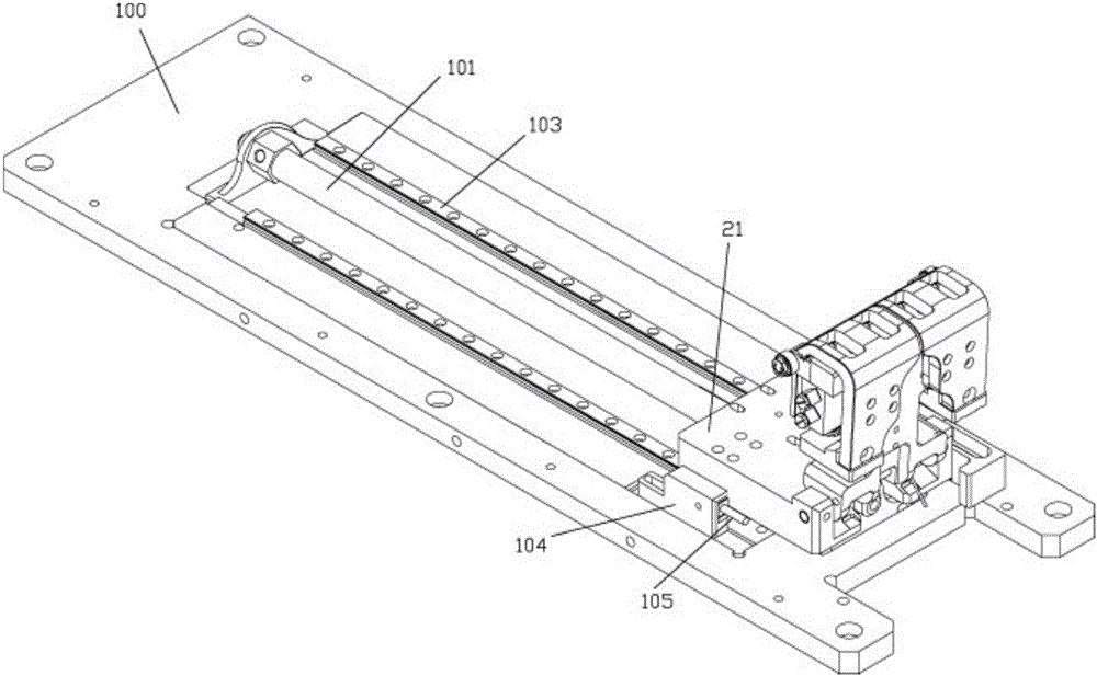
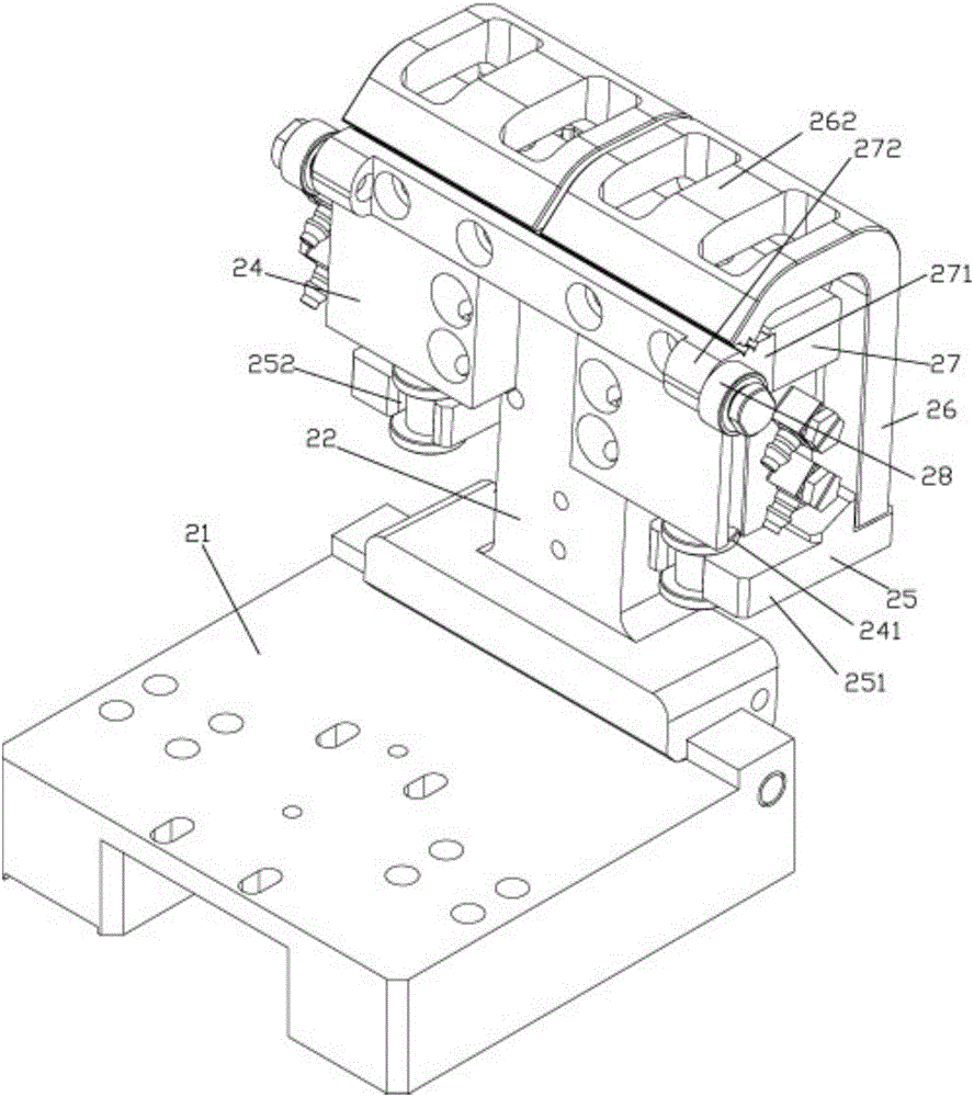
[0013] Examples, see e.g. Figures 1 to 7 As shown, a front jaw conveying mechanism for an automatic sheet material feeding mechanism includes a base plate 100 and a front jaw base 21, a rodless cylinder 101 is fixed in the middle of the base plate 100, and a slider 102 of the rodless cylinder 101 is fixed on There are front jaw bases 21, two sliding rails 103 are fixed on the base plate 100 on both sides of the rodless cylinder 101, and lateral moving blocks 29 are fixed on both sides of the bottom of the front jaw base 21, and the lateral moving blocks 29 are inserted into the sliding on track 103;

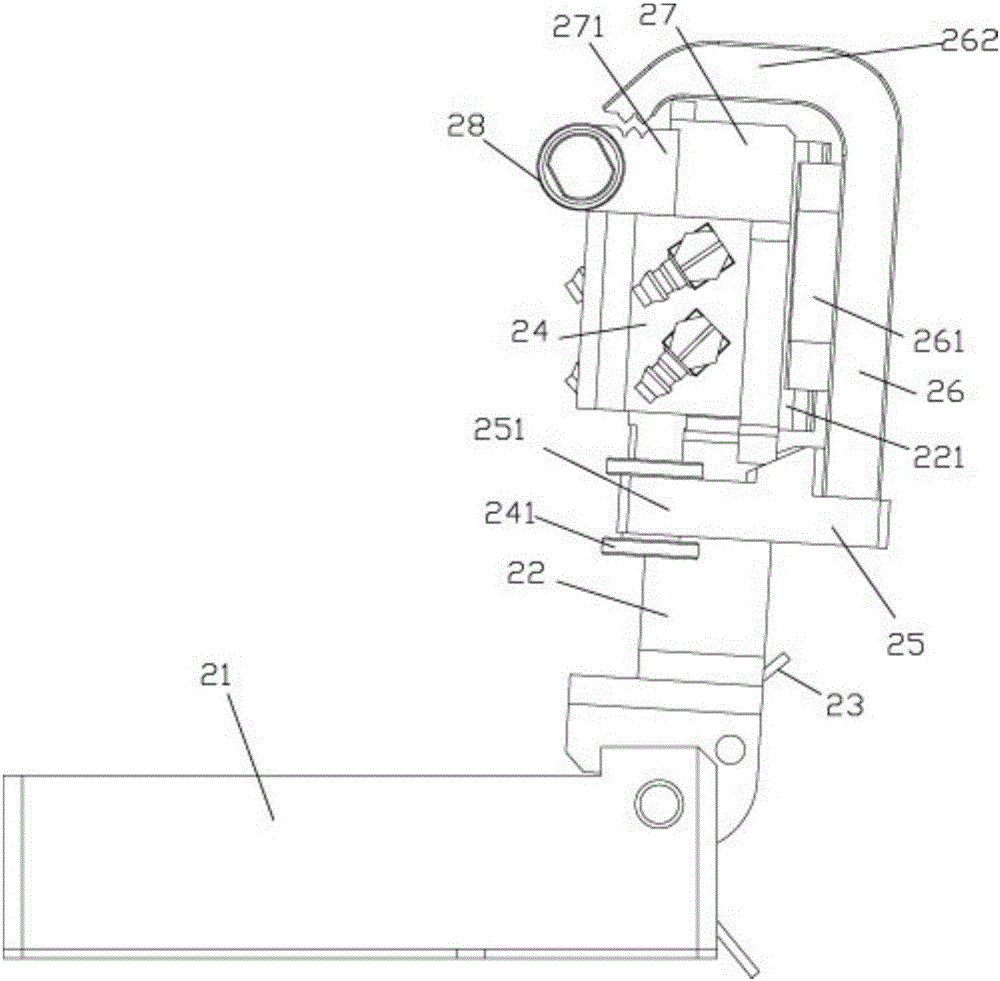
[0014] The right end of the front jaw base 21 is hinged with a rotating clamp base 22 through a pin shaft, and a torsion spring 23 is arranged on the pin shaft. One end of the torsion spring 23 is pressed against the rotating clamp base 22, and the other end is pressed against the front jaw base 21. On the front and rear sides of the rotating clamp seat 22, two front jaw cylind...


PUM


Abstract

The invention discloses a front clamping jaw conveying mechanism for an automatic sheet conveying mechanism. The front clamping jaw conveying mechanism comprises a base plate and a front clamping jaw base. A rodless air cylinder is fixedly arranged in the middle of the base plate. The front clamping jaw base is fixedly arranged on a sliding block of the rodless air cylinder. Two sliding tracks are fixedly arranged at the portions, on the two sides of the rodless air cylinder, of the base plate. Transverse moving blocks are fixedly arranged on the two sides of the bottom of the front clamping jaw base. The transverse moving blocks are inserted on the sliding tracks in a sleeving manner. A rotating clamping base is arranged at the right end of the front clamping jaw base through a pin shaft in a hinging manner. A torsional spring is arranged on the pin shaft. One end of the torsional spring abuts against the rotating clamping base in a pressed manner, and the other end of the torsional spring abuts against the front clamping jaw base in a pressed manner. Two front clamping jaw air cylinders are fixedly arranged on the front and rear sides of the rotating clamping base. The front clamping jaw conveying mechanism is installed on equipment capable of clamping, tensioning and conveying sheets, used as a clamping device at the frontpart of the equipment and driven by the rodless air cylinder to move, so that the front clamping jaw conveying mechanism slides along the back face of a movable plate of the equipment by using rolling bearings as rollers, clamping is firm, and the clamping effect is good.

Description

Technical field: [0001] The invention relates to the technical field of material viscosity strength detection equipment, and more specifically relates to a front jaw conveying mechanism for an automatic sheet material feeding mechanism. Background technique: [0002] When the existing viscous materials in the form of flakes are produced, their viscosity needs to be tested, so as to ensure that the quality of the produced products is qualified, and the materials need to be transported before the detection, and the flakes need to be kept in tension at all times during the conveyance. tight state, but there is no such equipment now, let alone a clamping device that can clamp this sheet. Invention content: [0003] The purpose of the present invention is to overcome the deficiencies of the prior art, and provide a front jaw conveying mechanism for automatic sheet material feeding mechanism, which is installed on the equipment that can clamp and tighten the sheet material and t...

Claims


Application Information

Patent Timeline
IPC IPC(8): B65G47/22B65G47/74B65G49/00
Inventor 吕绍林汪炉生杨艳伟吕凯陈士海占枝武赵学军
Owner BOZHON PRECISION IND TECH CO LTD
Learn More