
Magnetic separator

A magnetic separator and magnetic separation device technology, which is applied in the direction of pile separation, object separation, and thin material processing, can solve the problems of high labor cost, easy to stick together, and low efficiency of manual separation, so as to reduce labor cost and cost Low cost and the effect of improving production efficiency

Inactive Publication Date: 2015-10-21
重庆市小榄电器有限公司
View PDF0 Cites 0 Cited by
  • Summary
  • Abstract
  • Description
  • Claims
  • Application Information

AI Technical Summary

Problems solved by technology

[0002] In the prior art, when the valve plate is processed or assembled with other objects, it is usually necessary to manually separate the stacked valve plates one by one and send them to the next processing area, but because the valve plate is very thin and Its surface is usually attached with anti-rust oil to prevent it from rusting, so the two valve plates are easy to stick together. In actual operation, the channel needs to separate the valve plates manually, but the manual separation efficiency is low and not It is suitable for the mass production of valve plates, and now the labor cost is high. This mode of operation is no longer accepted by enterprises, so it is necessary to design a device without manual intervention to replace it.

Method used


Image

  • Magnetic separator

Examples


Embodiment Construction

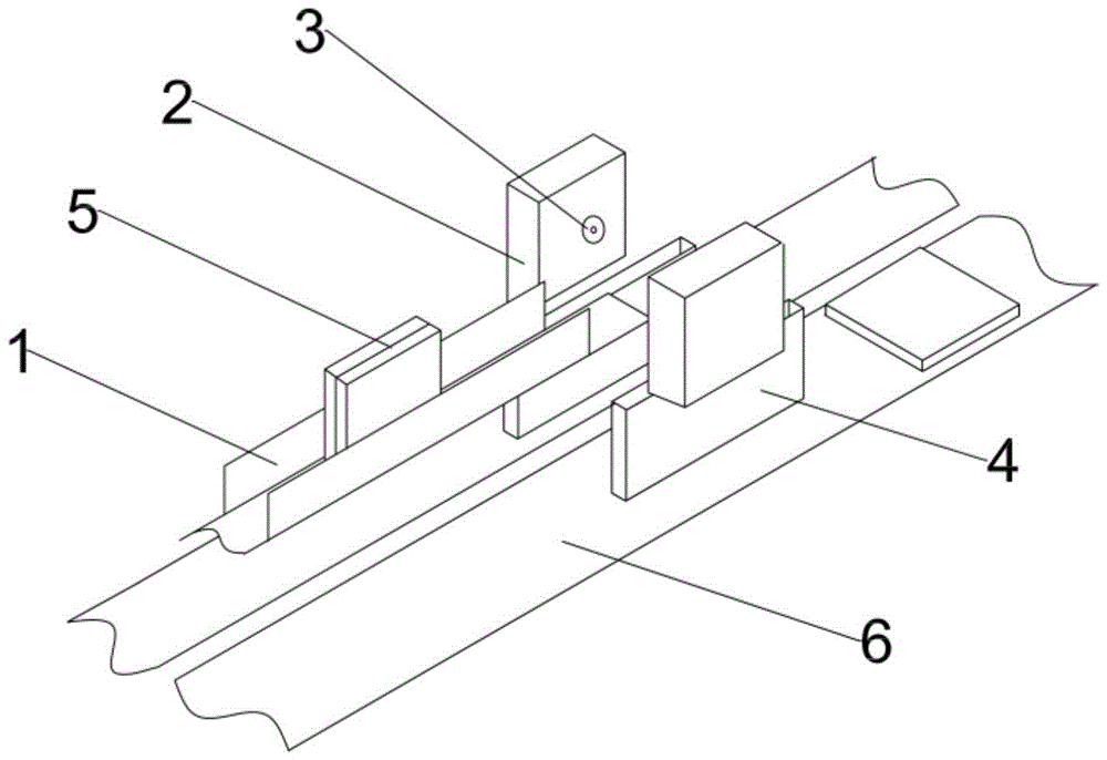
[0014] The reference signs in the description of the drawings are: conveying trough 1, electromagnet 2, photoelectric sensor 3, channel 4, valve plate 5, and conveyor belt 6.

[0015] like figure 1 As shown, this technical solution provides a magnetic separator, including a transmission part and a separation part. The transmission part includes a conveying trough 1 for the vertical transmission of the valve plate 5, so that the two plates of the valve plate 5 correspond to the direction of the electromagnet 2 to facilitate separation. Electromagnet 2 to its separation.

[0016] The separation part includes two electromagnets 2, and the two electromagnets 2 are respectively fixedly installed on both sides of the conveying tank 1, and the two side walls of the conveying tank 1 corresponding to the electromagnets 2 are provided with notches, and the width of the notches is at least larger than that of the valve. The length of the plate 5, so that the electromagnet 2 will not be ...


PUM


Abstract

The invention relates to separation equipment, in particular to a magnetic separator. The magnetic separator comprises a conveying portion and a separation portion. The conveying portion comprises a conveying groove enabling valve plates to be vertically conveyed. The separation portion comprises two electromagnets. The two electromagnets are correspondingly arranged on the two sides of the conveying groove respectively. Photoelectric sensors are embedded in the electromagnets and communicated with electromagnet starting switches. A through groove where one single valve plate passes is correspondingly formed below each electromagnet, and a conveying belt used for receiving the valve plate is correspondingly arranged below each through groove. By the implementation of the technical scheme, the magnetic separator has the advantages that the valve plates can be separated by means of the equipment composed of the electromagnets, the conveying groove, the photoelectric sensors and the other simple devices; the cost is low; production efficiency is improved and the labor cost is reduced without manual intervention.

Description

technical field [0001] This invention relates to separation equipment, and more particularly to magnetic separators. Background technique [0002] In the prior art, when the valve plate is processed or assembled with other objects, it is usually necessary to manually separate the stacked valve plates one by one and send them to the next processing area, but because the valve plate is very thin and Its surface is usually attached with anti-rust oil to prevent it from rusting, so the two valve plates are easy to stick together. In actual operation, the channel needs to separate the valve plates manually, but the manual separation efficiency is low and not It is suitable for the mass production of valve plates, and the labor cost is high nowadays. This mode of operation is no longer accepted by enterprises, so it is necessary to design a device that does not require manual intervention to replace it. Contents of the invention [0003] The purpose of the present invention is ...

Claims


Application Information

Patent Timeline
Patent Type & Authority Applications(China)
IPC IPC(8): B65H3/46
Inventor 沈春蓝
Owner 重庆市小榄电器有限公司
Learn More