A lifting pulley block displacement mechanism

A technology of displacement mechanism and pulley block, which is applied in the direction of traveling mechanism, load block, load suspension components, etc., which can solve the problems of reduced operating efficiency, torsion of the spreader, inaccurate positioning, etc., and achieve the effect of improving the operating efficiency of the driver

Active Publication Date: 2017-02-01
SHANGHAI ZHENHUA HEAVY IND
View PDF5 Cites 0 Cited by
  • Summary
  • Abstract
  • Description
  • Claims
  • Application Information

AI Technical Summary

Problems solved by technology

However, in the double spreader operation mode, the suspension steel wire rope becomes a straight-eight figure when the upper frame is separated, and the spreader is twisted and swayed, resulting in inaccurate positioning, which leads to problems such as difficult box alignment and reduced operating efficiency.

Method used


Image

  • A lifting pulley block displacement mechanism
  • A lifting pulley block displacement mechanism
  • A lifting pulley block displacement mechanism

Examples


Embodiment Construction

[0017] Embodiments of the present invention will now be described in detail with reference to the accompanying drawings. Wherever possible, the same numbers will be used throughout the drawings to refer to the same or like parts. In addition, although the terms used in the present invention are selected from well-known and commonly used terms, some terms mentioned in the description of the present invention may be selected by the applicant according to his or her judgment, and the detailed meanings thereof are set forth herein described in the relevant section of the description. Furthermore, it is required that the present invention be understood not only by the actual terms used, but also by the meaning implied by each term.

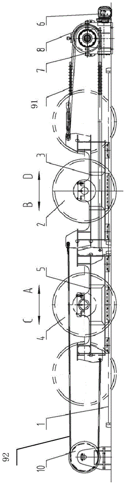
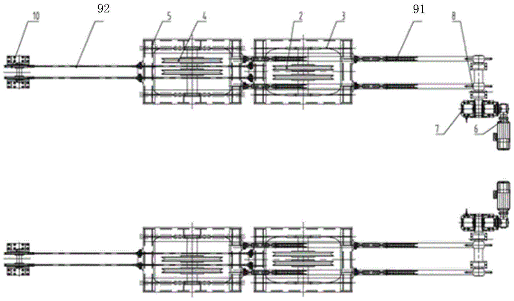
[0018] figure 1 A schematic structural diagram of an embodiment of the present invention is shown. figure 2 A schematic top view of one embodiment of the invention is shown. As shown in the figure, a lifting pulley block displacement mechanism 100...


PUM


Abstract

The invention provides a hoisting pulley assembly displacement mechanism. The hoisting pulley assembly displacement mechanism comprises a vehicle frame, and also comprises two sets of pulley assembly displacement devices symmetrically arranged along the center line of the vehicle frame, and each set of the pulley assembly displacement devices comprises: a track arranged on the vehicle frame; a seaside driving pulley trolley arranged on the track; a seaside hoisting pulley assembly fixed on the seaside driving pulley trolley; a landside driven pulley trolley arranged on the track; a landside hoisting pulley assembly fixed on the landside driven pulley trolley; a speed reduction motor arranged at one side of the seaside driving pulley trolley; and a speed reduction box, wherein the input shaft of the speed reduction box is coupled to the output shaft of the speed reduction motor. A quay crane having two single-suspender and double-suspender work modes and adopting the hoisting pulley assembly displacement mechanism can effectively alleviate the influences of inertia force and wind power on suspenders when the vehicle starts and brakes under a single hoisting system in order to improve the working efficiency of a driver.

Description

technical field [0001] The invention relates to hoisting machinery, in particular to a displacement mechanism of a hoisting pulley block. Background technique [0002] With the vigorous development of international container transportation, container yards, especially container yards that are dedicated to containers, have higher and higher requirements on the efficiency, automation, and failure rate of access equipment. With the "three super" type container ships put into use, 3E-class quay cranes came into being. It puts forward new functional requirements for the running trolley, and it is necessary to use double spreaders to lift double 40-foot containers at the same time under the single lifting system. [0003] The lifting pulley blocks on the existing running trolley are fixed on the vehicle frame, and the distance between the lifting pulley blocks is constant. In the single spreader operation mode, the wire rope connecting the hoisting pulley block on the frame and ...

Claims


Application Information

Patent Timeline
Patent Type & Authority Patents(China)
IPC IPC(8): B66C9/14B66C13/06
CPCB66C9/14B66C11/20B66C13/06
Inventor 张砾张明海江华黄小辉
Owner SHANGHAI ZHENHUA HEAVY IND
Why Eureka
Try Eureka