Mechanical seal with shallow slots

A mechanical seal, shallow groove technology, applied in the direction of engine seals, mechanical equipment, engine components, etc., can solve the problems of inability to directly process, poor machinability, insufficient machining accuracy and surface roughness.

Inactive Publication Date: 2015-10-21
霍凤伟
View PDF8 Cites 6 Cited by
  • Summary
  • Abstract
  • Description
  • Claims
  • Application Information

AI Technical Summary

Problems solved by technology

These three-dimensional convergent dynamic pressure grooves generally have the characteristics of fine structure, high precision, and strict roughness requirements. The machinability is generally poor, and some are difficult to process, and some cannot even be processed directly. Now, high-energy laser beam Approximate forming by layered processing has shortcomings in processing accuracy and surface roughness

Method used


Image

  • Mechanical seal with shallow slots
  • Mechanical seal with shallow slots
  • Mechanical seal with shallow slots

Examples


Embodiment 1

[0097] Example 1: Please refer to figure 1 , figure 2 with image 3 .

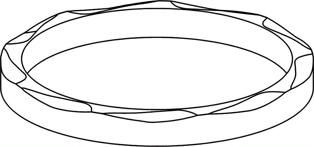
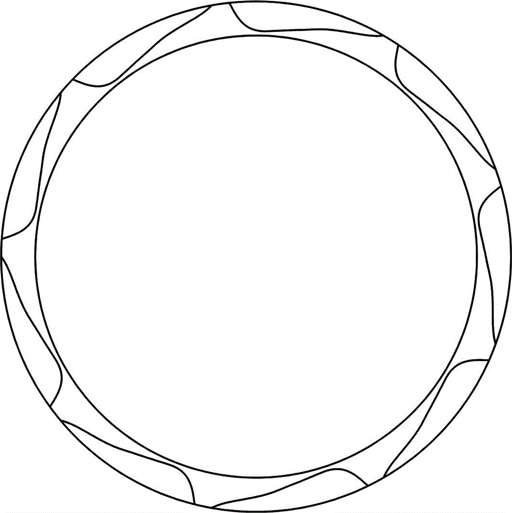
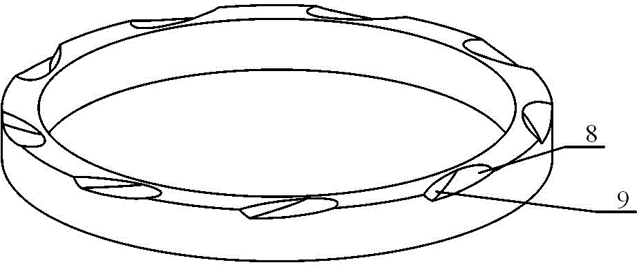
[0098] A shallow groove mechanical seal, including a static ring and a moving ring, on the sealing end face of the moving ring, or on the sealing end face of the static ring, or on both sealing end faces at the same time, a shallow groove is provided, and when working, the two The sealing end faces of the rings are close to each other, and there is a sealing medium in the gap. The rotating shaft drives the moving ring to rotate relative to the static ring. The gap between the two sealing end surfaces leaks. The shallow groove is a curved surface groove. The bottom surface of the curved surface groove is a curved surface. The curved surface is a circle with a radius of 175 mm and an inclination angle of 0.0002 radians to the sealing end surface. The straight line parallel to the axis of the ring and passing through the center of the circumference is a part of the smooth continuous curved surface formed ...

Embodiment 2

[0101] Example 2: Please refer to Figure 4 , Figure 5 , Image 6 with Figure 7 .

[0102] The difference from Embodiment 1 lies in the different shapes of the curved grooves. Figure 4 Indicates the shape of the curved surface groove on the sealing end surface in Example 2, Figure 5 yes Figure 4 A top view of the shape shown, Image 6 yes Figure 4 The schematic diagram of the surface groove formation is shown, Figure 7 yes Image 6 Top view of the schematic shown. The said motion rule is that the circle inclined to the seal end face performs a composite motion consisting of a linear motion slightly inclined to the seal end face and a rotation around the axis of the seal ring. In this embodiment, the curved surface groove formed is composed of a smooth curved surface, which smoothly transitions to the sealing end surface without steep side walls, and the intersection line between the curved surface and the sealing end surface is a smooth curve, and the distance...

Embodiment 3

[0103] Example 3: Please refer to Figure 8 , Figure 9 with Figure 10 .

[0104] The difference from the previous embodiments lies in the different shapes of the curved grooves. Figure 8 Indicates the shape of the curved surface groove on the sealing end surface in Example 3, Figure 9 yes Figure 8 A top view of the shape shown, Figure 10 yes Figure 8 Schematic diagram of surface groove formation shown. The motion rule is a composite motion composed of a rotation with a straight line parallel to the sealing end surface as an axis and a rotation around the axis of the seal ring. In this embodiment, the intersection line between the curved surface groove and the sealing end surface is a smooth curve, and the curved surface groove is generally symmetrical with respect to the radial line of the sealing ring. Generate sufficient hydrodynamic pressure effect, suitable for occasions that require mechanical seals to rotate in both directions.


PUM


Abstract

The invention relates to a mechanical seal with shallow slots. The mechanical seal with shallow slots is characterized in that the shallow slots with bottom surfaces as curved surfaces are formed in sealing end surfaces of a dynamic ring and a static ring, wherein each curved surface is one part of a smooth continuous curved surface formed by a motion track generated when a circumference moves in a three-dimensional space according to the motion law; and each curved-surface slot is of a three-dimensional convergent shape which becomes more and more shallow and narrow from a high pressure side to a low pressure side, and has stronger convergence characteristics. Compared with a common mechanical seal with shallow slots, the thickness or the rigidity of a fluid film under the same condition is greater, the stability and the reliability are higher, the service life is longer, the curve-surface slots can be precisely formed by adopting a grinding method, and the processing precision is high. The mechanical seal with shallow slots is suitable for sealing various rotary fluid machines.

Description

technical field [0001] The invention belongs to the field of mechanical seals, and relates to a shallow groove mechanical seal, in particular to a shallow groove mechanical seal in which the groove bottom surface is a curved surface on the sealing end surface, and is suitable for various forms of pumps, compressors, separators, expanders, Axial end face seals of rotating machines such as steam turbines, engines, and reactors. Background technique [0002] The shallow groove mechanical seal is to open a series of dynamic pressure grooves with a depth of micron on the flat end surface of one of the sealing rings, such as spiral grooves, arc grooves, leaf grooves, T grooves, Y grooves, L grooves, Straight grooves and various special-shaped grooves, etc., during operation, due to the dynamic pressure effect of the dynamic pressure groove, the pressure of the sealing fluid entering the groove will increase, and the pressure will act on the sealing end faces of the dynamic and sta...

Claims


Application Information

Patent Timeline
Patent Type & Authority Applications(China)
IPC IPC(8): F16J15/16
CPCF16J15/16
Inventor 霍凤伟
Owner 霍凤伟
Why Eureka
Try Eureka