
Butterfly valve with both-way sealing function

A two-way sealing and functional technology, applied in the direction of lift valves, valve devices, engine components, etc., can solve the problems of affecting the sealing performance of the sealing ring, position deviation, medium backflow, etc., achieve reliable two-way sealing, and overcome the effect of insufficient sealing force

Active Publication Date: 2015-10-21
FANGZHENG VALVE GRP
View PDF7 Cites 1 Cited by
  • Summary
  • Abstract
  • Description
  • Claims
  • Application Information

AI Technical Summary

Problems solved by technology

[0003] At present, the butterfly valves on the market basically realize the sealing effect through the sealing ring on the butterfly plate. In this way, the sealing ring is prone to position shift or even drop due to the pressure of the medium during use, which will affect the sealing effect. Butterfly valves set the inner wall of the valve seat to be inclined on one side, so as to avoid the position of the sealing ring from shifting or falling off when it is subjected to the positive force of the medium, and the sealing ring is stressed to increase the sealing performance, but this can only play a role. One-way good sealing effect, when the butterfly plate is turned to close the valve body, there is likely to be a reverse force of the medium, and the general butterfly valve directly affects the sealing performance of the sealing ring when the reverse force is applied, so that the sealing ring cannot be tightly connected to the inner wall of the valve seat Conflict, and then there will be medium backflow, and a good two-way sealing effect cannot be achieved, which needs further improvement

Method used


Image

  • Butterfly valve with both-way sealing function
  • Butterfly valve with both-way sealing function
  • Butterfly valve with both-way sealing function

Examples


Embodiment Construction

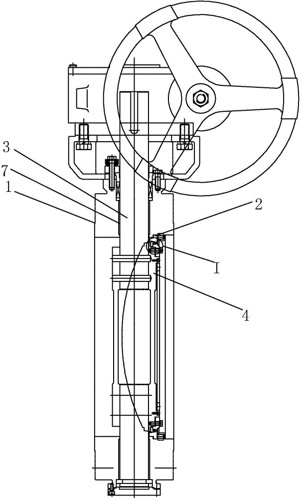
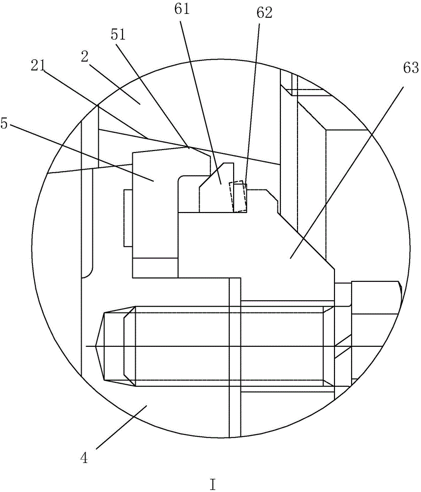
[0016] refer to Figure 1 to Figure 2 The embodiment of the butterfly valve with bidirectional sealing function of the present invention will be further described.

[0017] A butterfly valve with two-way sealing function, comprising a valve body 1, a valve seat 2 and a valve stem 3, the valve seat 2 is set in the valve body 1, the valve stem 3 is provided with a butterfly plate 4, and the butterfly plate 4 is provided with a sealing ring 5, and the sealing ring 5 is in conflict with the inner wall of the valve seat 2, the inner wall of the valve seat 2 is provided with an inclined part 21, and the inclined part 21 is arranged around the inner wall of the valve seat 2, and the opening of the side of the valve seat 2 opposite to the liquid inlet is larger than that of the other side, wherein the sealing The cross section of the ring 5 is in the shape of a "7", and the top of the sealing ring 5 is provided with a top portion 51, and the top portion 51 conflicts with the inner wal...


PUM


Abstract

The invention discloses a butterfly valve with the both-way sealing function. According to the technical scheme, the butterfly valve is characterized in that an inclination part is arranged on the inner wall of a valve seat, and the inclination part surrounds the inner wall of the valve seat; an opening in the side, opposite to a liquid inlet, of the valve seat is larger than an opening of the other side; a sealing ring is in line contact with the inclination part. On one hand, the inclination part is arranged on the inner wall of the valve seat and surrounds the inner wall of the valve seat, and therefore when the butterfly valve is used, the function of well blocking the sealing ring can be achieved when the butterfly valve is subjected to medium forward direction acting force, and the sealing ring is pressurized and can make better close contact with the inclination part on the valve seat; on the other hand, the sealing ring is in line contact with the inclination part on the valve seat, and when the butterfly valve is closed, the butterfly valve is in the optimal line contact sealing all the time; the sealing ring can be automatically offset in the axial direction and the radial direction, the insufficiency of the medium reverse acting sealing force is overcome, and both-way sealing is reliable.

Description

technical field [0001] The invention relates to the field of valves, more specifically, it relates to a butterfly valve with bidirectional sealing function. Background technique [0002] Valves are the control components in the fluid conveying system. They have the functions of cut-off, adjustment, flow diversion, reverse flow prevention, pressure stabilization, flow diversion or overflow pressure relief. Valves, ball valves and butterfly valves, etc., are widely used in natural gas long-distance pipelines, metallurgy, hydropower, thermal power, urban water supply and drainage, farmland drainage and irrigation and other industries, and are suitable for natural gas, coal gas, steam, air, water, etc. In the pipeline system, it is used to cut off or connect the medium. The butterfly valve mainly includes a valve body, a valve seat and a valve stem. The opening and closing of the body. [0003] At present, the butterfly valves on the market basically realize the sealing effect...

Claims


Application Information

Patent Timeline
Patent Type & Authority Applications(China)
IPC IPC(8): F16K1/226F16K1/42
CPCF16K1/2261F16K1/42
Inventor 夏福民周晓丰郑毅黔瞿山入刘献跃董文龙
Owner FANGZHENG VALVE GRP
Learn More