Novel heat exchange pipe

A heat exchange tube, a new type of technology, applied in tubular elements, heat exchange equipment, lighting and heating equipment, etc., can solve the problems of heat exchange tube length, affect heat exchange efficiency, increase equipment length, etc., and achieve high heat exchange efficiency. , The effect of reducing the horizontal area and reducing the length of the horizontal space

Inactive Publication Date: 2015-10-21
JIANGYIN BAOLONG ELECTRONICS
View PDF0 Cites 0 Cited by
  • Summary
  • Abstract
  • Description
  • Claims
  • Application Information

AI Technical Summary

Problems solved by technology

[0002] Existing heat exchange tubes are all long and straight tubes, and a larger heat exchange area is often required during heat exchange. At this time, the required heat

Method used


Image

  • Novel heat exchange pipe

Examples


Embodiment Construction

[0008] All features disclosed in this specification, or steps in all methods or processes disclosed, may be combined in any manner, except for mutually exclusive features and / or steps.

[0009] Any feature disclosed in this specification, unless specifically stated, can be replaced by other alternative features that are equivalent or have similar purposes. That is, unless expressly stated otherwise, each feature is one example only of a series of equivalent or similar features.

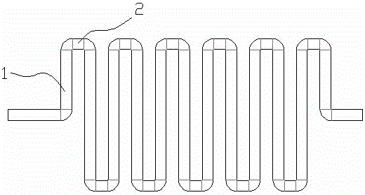
[0010] like figure 1 The new heat exchange tube shown includes a tube body 1 with several bends 2, and the two ports of the tube body 1 are on the same horizontal plane. Since the present invention has several bends, the transverse area of ​​the heat exchange tube is greatly reduced, the heat exchange area is increased while the length of the transverse space is reduced, and the heat exchange efficiency is high.

[0011] The present invention is not limited to the foregoing specific embodiments. Th...


PUM


Abstract

The invention discloses a novel heat exchange pipe which comprises a pipe body (1). The pipe body (1) is provided with multiple bends (2). The two ends of the pipe body (1) are located on the same horizontal plane. Due to the fact that the pipe is provided with the bends, the transverse area of the heat exchange pipe is greatly reduced, the transverse space length is reduced, the heat exchange area is increased, and heat exchange efficiency is high.

Description

technical field [0001] The invention relates to a novel heat exchange tube. Background technique [0002] Existing heat exchange tubes are all long and straight tubes, and a large heat exchange area is often required during heat exchange. At this time, the required heat exchange tubes are longer, which greatly increases the length of the entire equipment. If shorter The heat exchange tube will greatly affect the efficiency of heat exchange. Contents of the invention [0003] In order to solve the problem that the current heat exchange tube occupies too much space, the present invention provides a new type of heat exchange tube, which includes a tube body 1 with several bends 2, and the two ports of the tube body 1 on the same level. [0004] The beneficial effects of the present invention are: [0005] Since the present invention has several bends, the transverse area of ​​the heat exchange tube is greatly reduced, the heat exchange area is increased while the length of...

Claims


Application Information

Patent Timeline
IPC IPC(8): F28F1/08
Inventor 曹亚静
Owner JIANGYIN BAOLONG ELECTRONICS
Why Eureka
Try Eureka