Unmanned aerial vehicle

A technology of unmanned aerial vehicles and airframes, applied in the field of aircraft, can solve the problems that the wings 3 are easy to break, and achieve the effects of fast protective action, strong protection ability, and reduced lateral area

Active Publication Date: 2019-02-15
何雪琴
View PDF7 Cites 2 Cited by
  • Summary
  • Abstract
  • Description
  • Claims
  • Application Information

AI Technical Summary

Problems solved by technology

[0004] The operator usually holds the remote control to control the drone wirelessly; affected by the operator's actual operation proficiency, once the balance of the entire drone is not controlled, it is affected by the special structure of the drone, especially the arm The wing 3 on the 2 is located at the end of the arm 2, and the position of the wing 3 is the most vulnerable. Once it touches the ground and crashes, the wing 3 is very easy to break

Method used


Image

  • Unmanned aerial vehicle
  • Unmanned aerial vehicle
  • Unmanned aerial vehicle

Examples


Embodiment 1

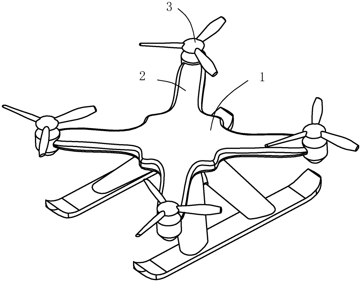
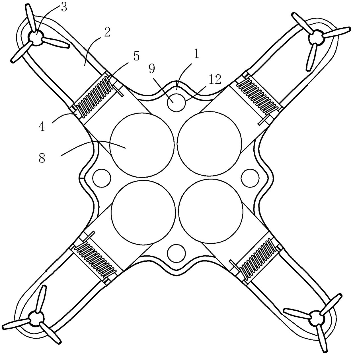
[0038] An unmanned aerial vehicle disclosed by the present invention includes a body 1 and a plurality of arms 2. In this embodiment, the number of arms 2 is four, and the four arms 2 are evenly distributed around the body 1. The arms 2 deviate from The end of the body 1 is provided with wings 3, and each wing 3 is driven forward and reverse by a motor.

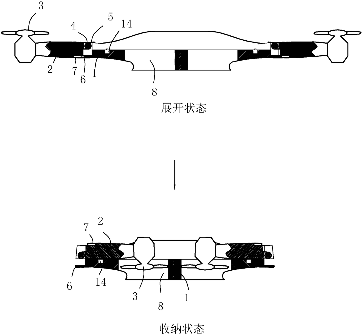
[0039] One end of the machine arm 2 is hinged to the body 1 through the hinge shaft 4, the hinge shaft 4 is provided with a torsion spring 5, and the body 1 is provided with four through holes 8 corresponding to the wings 3, the number is also four, and the torsion spring 5 is used to drive The arm 2 is turned over to the side of the body 1 and the wing 3 is close to the outside of the body 1 . After the arm 2 is folded, the wing 3 enters the through hole 8 correspondingly.

[0040] On each wing 3, a telescopic power assembly 7 is installed, and the telescopic power assembly 7 selects a cylinder, and a limit hole 6 is provide...

Embodiment 2

[0043]Embodiment 2: The difference from Embodiment 1 is that the following technical solutions are added. The body 1 is provided with a sliding groove 15 and a trigger groove 16. One end of the sliding groove 15 runs through the body 1 near the hinge point of the machine arm 2. On the other side, a protective rod 17 is provided for sliding in the sliding groove 15, and one end of the triggering groove 16 communicates with the inside of the sliding groove 15, and the other end communicates with the side wall of the body 1, and a triggering rod 19 is provided for sliding in the triggering groove 16 to protect The end of the rod 17 is provided with a first inclined guide surface 18, and the end of the trigger lever 19 is provided with a second inclined guide surface 20, the first inclined guide surface 18 is offset against the second inclined guide surface 20, and the trigger rod 19 deviates from the second inclined guide surface. The end of the surface 20 protrudes from the outer...


PUM


Abstract

The invention relates to an unmanned aerial vehicle. The unmanned aerial vehicle comprises a fuselage and a plurality of vehicle arms which are evenly distributed around the fuselage; wings are arranged at the ends, deviating from the fuselage, of the vehicle arms; one ends of the vehicle arms are hinged to the fuselage through hinging shafts, the hinging shafts are provided with torsional springs, and the torsional springs are used for driving the vehicle arms to be overturned towards the side of the fuselage and enabling the wings to get close to the outer side of the fuselage; the unmannedaerial vehicle further comprises telescopic power assemblies mounted on the wings, limiting holes are formed in the outer side wall of the fuselage, and telescopic heads of the telescopic power assemblies can be inserted into the limiting holes and enable the vehicle arms to be kept in an extending state; and the telescopic power assemblies can be controlled by a remote controller to generate thetelescopic action. The unmanned aerial vehicle has the effect of being capable of significantly reducing the damage degree to the wings during crash.

Description

technical field [0001] The invention relates to the technical field of aircraft, in particular to an unmanned aerial vehicle. Background technique [0002] Unmanned aircraft, referred to as "unmanned aerial vehicle", or "UAV" in English, is an unmanned aircraft that is controlled by radio remote control equipment and its own program control device, or is completely or intermittently operated autonomously by an on-board computer. [0003] Traditional UAV structure see figure 1 , its structure includes a body 1, a plurality of arms 2 are installed on the body 1, and a plurality of arms 2 form a circular array centered on the middle of the body 1, one end of the arm 2 is connected to the body 1, and the other end extends to the body 1 In addition, the end of the arm 2 facing away from the body 1 is provided with a motor and a wing 3, and the motor drives the wing 3 to rotate; in actual use, the motor drives the wing 3 to rotate, the wing 3 stirs the air, and the airflow is dir...

Claims


Application Information

Patent Timeline
Patent Type & Authority Applications(China)
IPC IPC(8): B64C1/30B64C27/00B64C27/08
CPCB64C1/30B64C27/006B64C27/08B64U30/20B64U10/10
Inventor 张凉英
Owner 何雪琴
Why Eureka
Try Eureka