
Highway high-speed rail transit system and realization method

A high-speed rail and transportation system technology, applied in the field of highway high-speed rail transportation system, to achieve low cost, improve transportation capacity, and enhance safety performance

Active Publication Date: 2015-10-21
JINAN ZHAOYUE ELECTRONICS CO LTD
View PDF5 Cites 3 Cited by
  • Summary
  • Abstract
  • Description
  • Claims
  • Application Information

AI Technical Summary

Problems solved by technology

[0003] The purpose of the present invention is to solve the problem that existing highway lane markings and iron guardrails are subject to human factors and weather visibility factors to cause traffic accidents, and provide a highway high-speed rail transit system and its implementation method, which can Under low-visibility weather conditions, the road and vehicle dynamic data generated by road facilities are provided to driving vehicles, so that vehicles can generate vehicles according to high-speed rail traffic rules high High-speed driving curve, that is, to make each vehicle pass at a high speed with the cooperation of maintaining a safe distance between vehicles and vehicle speed, fundamentally avoiding traffic accidents, completely solving the problem of traffic congestion, and improving the transportation capacity of existing roads

Method used


Image

  • Highway high-speed rail transit system and realization method
  • Highway high-speed rail transit system and realization method
  • Highway high-speed rail transit system and realization method

Examples


Embodiment Construction

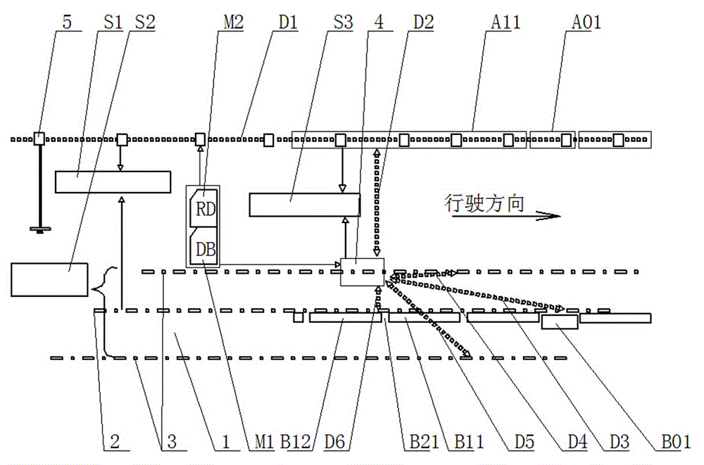
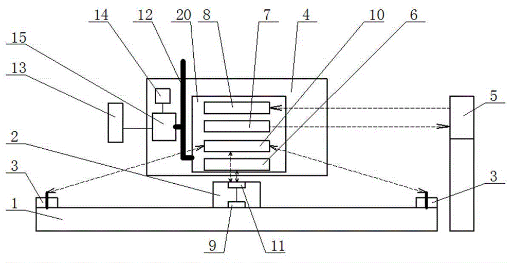
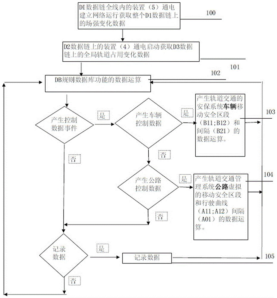
[0026] A highway high-speed rail transit system according to the present invention comprises a lane 1 and a vehicle-mounted travel controller 4. A plurality of pilot spikes 2 are arranged at intervals on the center line of the lane 1, and navigation spikes 3 are arranged on both sides of the lane 1. The lane 1 The distance between the navigation spikes 3 on both sides and the center line of the lane 1 is equal, and the on-board travel controller 4 is connected with the steering gear and the electronic control unit of the vehicle through the CAN bus 12. The navigation spikes 3 on both sides transmit radio signals, and receive the radio signals fed back by the pilot spikes 2 and the navigation spikes 3 on both sides, and simultaneously analyze the field strength of the radio signals of the pilot spikes 2 and the navigation spikes 3 on both sides A first information memory 9 is installed in the pilot spike 2, and a near-field communication unit 11 is arranged on the first informat...


PUM


Abstract

The invention relates to a highway high-speed rail transit system. The highway high-speed rail transit system includes a lane and a vehicle-mounted driving controller; a plurality of pilotage track spikes which are arranged at intervals are arranged on the center line of the lane; two sides of the lane are both provided with navigation track spikes; the distances between the navigation track spikes at the two sides of the lane and the center line of the lane are equal; and the vehicle-mounted driving controller is connected with a steering gear box and an electronic control unit of a vehicle through a CAN bus, and receives radio signals fed back by the pilotage track spikes and the navigation track spikes at the two sides of the lane, and analyzes the magnitude of the field intensity of the radio signals of the pilotage track spikes and the navigation track spikes at the two sides of the lane. With the highway high-speed rail transit system of the invention adopted, the single wheeltrack type mechanical principle of existing highway railway track rail transit and urban rail transit can be changed fundamentally; tracks are replaced by semiconductor chips; high-speed travelling of common vehicles according to rail transit can be realized; vehicles on electronic highway tracks can leave the electronic highway tracks to stop at stations, and can be marshaled to enter the tracks; and therefore, electronic highway rails have higher efficiency than wheeltrack tracks do.

Description

technical field [0001] The invention relates to a road traffic system in the field of road traffic facilities and traffic signals, in particular to a highway, high-speed rail traffic system and its realization method. Background technique [0002] Existing highway facilities traffic management system and security system mainly prevent traffic accidents by means of lane markings, iron guardrails, reflective luminous spikes and outline markers, reflective and reflective road signs to indicate drivers and speed limits on road sections. However, traffic accidents and traffic jams have always been major problems restricting the capacity and safety of road transportation. On the one hand, road traffic is greatly affected by the weather. The distance is greatly reduced, and the transportation speed and transportation safety will be reduced. On the other hand, subjective factors such as driver rushing, speeding, and fatigue driving will also pose potential threats to the transportat...

Claims


Application Information

Patent Timeline
Patent Type & Authority Applications(China)
IPC IPC(8): G08G1/09G08G1/16G08G1/01
Inventor 高肇岳
Owner JINAN ZHAOYUE ELECTRONICS CO LTD
Learn More