High-efficiency classification thickener for tailings slurry

A technology of concentrator and material classification, applied in separation method, sedimentation separation, feeding/discharging device of sedimentation tank, etc., can solve the problems of poor solid-liquid separation effect, difficult to eliminate, equipment paralysis, etc. The effect of good effect, fast discharging speed and low cost of use

Inactive Publication Date: 2016-08-17
郴州德瑞福机械设备有限公司
View PDF11 Cites 0 Cited by
  • Summary
  • Abstract
  • Description
  • Claims
  • Application Information

AI Technical Summary

Problems solved by technology

[0009] 1. The traditional concentrator occupies a large area, and the solid-liquid separation effect is poor, which is inconvenient;
[0010] 2. When the underflow concentration of the high-efficiency thickener exceeds 50%, it is difficult to discharge. Adding flocculant at the feed port will easily cause paralysis of the equipment and inconvenient use;
[0011] 3. When the underflow concentration of the high-efficiency deep cone thickener is about 70%, it is also difficult to eliminate, and the material after flocculation is easy to hang on the wall, especially the ultra-fine material
For example, when the hydrophobicity of the material is good, when the underflow of the equipment is 70%, it cannot be eliminated at all, and it is inconvenient to use

Method used


Image

  • High-efficiency classification thickener for tailings slurry
  • High-efficiency classification thickener for tailings slurry
  • High-efficiency classification thickener for tailings slurry

Examples


Embodiment Construction

[0037] The present invention is described in detail below in conjunction with accompanying drawing and specific embodiment:

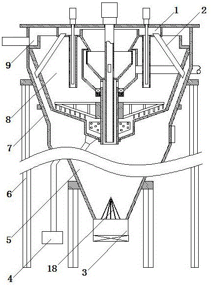
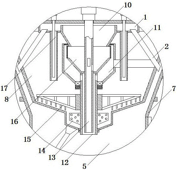
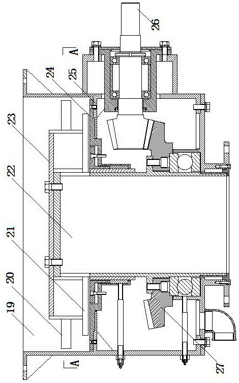
[0038] Such as figure 1 , figure 2 , image 3 , Figure 4 As shown, the tailings slurry high-efficiency classification concentrator of the present invention includes a support frame 6, a hopper 7 placed on the support frame 6, a material classification device, a stirring device, a return pipe 2, an overflow tank 9 and a discharge device 3 . The inside of the hopper 7 is divided into a classification chamber 8 and a material storage chamber 5 by a partition. A discharge port is provided at the bottom of the material storage chamber 5 . The material classifying device is placed in the classifying chamber 8 , and the material classifying device includes a primary material chamber 11 , a secondary material chamber 16 , a drop pressure chamber 10 and a circulation disc 1 . The primary material chamber 11 communicates with the material inlet pipe. The...


PUM


Abstract

The invention discloses an efficient classification and thickening machine for tailing slurry. The efficient classification and thickening machine comprises a supporting frame, a hopper, a material classifying device, a stirring device, a backflow pipe, an overflow tank and an unloading device. The hopper, the material classifying device, the stirring device, the backflow pipe, the overflow tank and the unloading device are arranged on the supporting frame. The hopper is internally divided into a classifying cavity and a material storing cavity through a partition plate. The material classifying device is arranged in the classifying cavity. The material classifying device comprises a primary material chamber, a secondary material chamber, a fall pressure chamber and a circulation plate. The stirring device comprises a first rotating shaft, a second rotating shaft and a slurry pump. The first rotating shaft and the second rotating shaft are hollow and are each in a cylindrical shape. One end of the first rotating shaft is connected with a motor in a transmission mode, and the other end of the first rotating shaft extends into the material storing cavity sequentially through the fall pressure chamber, the secondary material chamber and the primary material chamber. The first rotating shaft is sleeved with the second rotating shaft. The top end of the backflow pipe is arranged above the circulation plate and is lower than the top of the fall pressure chamber. The unloading device is arranged at the bottom of the material storing cavity and comprises a feed cylinder, a material guide cylinder, a spiral bevel gear and a transmission shaft.

Description

technical field [0001] The invention relates to a tailings treatment device, in particular to a tailings slurry high-efficiency classification thickener. Background technique [0002] Using thickening equipment to increase the concentration of tailings is a commonly used method at present. At present, thickeners are mainly divided into traditional thickeners, high-efficiency thickeners and high-efficiency deep cone thickeners. [0003] The traditional thickener consists of a shell, a driving device and a rake scraper. The solid particles suspended in the slurry in the thickening tank settle under the action of natural gravity, and the upper part becomes clarified water to separate the solid and liquid. The slime deposited at the bottom of the thickening tank is continuously scraped and collected by the rake scraper to the discharge port at the center of the bottom of the tank, while the clarified water overflows from the upper edge of the thickening tank. [0004] The str...

Claims


Application Information

Patent Timeline
Patent Type & Authority Patents(China)
IPC IPC(8): B01D21/02B01D21/01B01D21/24
Inventor 谢建雄梁新进
Owner 郴州德瑞福机械设备有限公司
Why Eureka
Try Eureka