Hot-straightening process for thin-gauge coiling rolling plate

A thermal straightening and thin-gauge technology, which is applied in the field of steel rolling, can solve problems such as the inability to set the roll gap, and achieve the effect of improving the qualified rate of thermal straightening

Inactive Publication Date: 2015-10-28
NANJING IRON & STEEL CO LTD
View PDF6 Cites 2 Cited by
  • Summary
  • Abstract
  • Description
  • Claims
  • Application Information

AI Technical Summary

Problems solved by technology

[0004] The purpose of the present invention is to provide a thermal straightening process for thin-gauge coiled and rolled plates. This process solves the problem that the steel plate with serious warping cannot bite into the straightening machine by adopting the method of quickly lifting the roll gap; The first-level automation system in the process) uses thermal inspection to position the head and automatically and dynamically set the roll gap, which solves the problem that the roll gap cannot be set under the load condition of the leveler, and finally realizes the rolling of warped heads Effective straightening of boards
[0006] A thermal straightening process for thin-gauge coiled plates, characterized in that: the process solves the problem that the steel plate with warped heads cannot bite into the straightening machine by adopting the method of quickly lifting the roll gap; the head is positioned by using thermal inspection And trigger the first-level automatic and dynamic setting of the roll gap, which solves the problem that the roll gap cannot be set under the load condition of the leveler, and finally realizes the effective straightening of the warped coil

Method used


Image

  • Hot-straightening process for thin-gauge coiling rolling plate
  • Hot-straightening process for thin-gauge coiling rolling plate
  • Hot-straightening process for thin-gauge coiling rolling plate

Examples


Embodiment

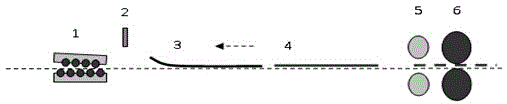
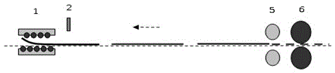
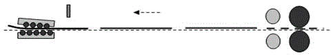
[0021] A thermal straightening process for rolled sheet with 5mm yield strength and 350MPa head warp. The roll diameter and roll distance of the leveler used in this process are 215mm and 230mm respectively, and the maximum inclination of the roll box is 8mm. The rolled piece cannot normally bite into the leveler due to the warping of the head. The total length of the rolled piece is about 200m, and the distance from the leveler to the rolling mill is 135m. Straightening and steel throwing form a linkage. The process requires that the entrance roll gap of the straightener is 0mm, and the exit roll gap is 5mm. Quickly lift the roll gap to make the warped plate pass through the straightening machine smoothly, and track the position of the steel plate head through the thermal inspection before the machine through the first stage. After the steel plate head passes through the straightener, the first stage automatically sets the roll gap and completes. Straighten.

[0022] The sp...


PUM

PropertyMeasurementUnit
yield strengthaaaaaaaaaa

Abstract

The invention discloses a hot-straightening process for a thin-gauge coiling rolling plate. When a straightener operator finds the head part of the coiling rolling plate is warped, and the steel plate cannot be normally gripped into the straightener, a roll container fast lifting button is pressed immediately, so that a straightener roll container is fast lifted to a preset position, and meanwhile, a first stage calculates and tracks the position of the head part of the steel plate by utilizing a heat detector in front of the straightener, the roll speed and time; when the head part of the steel plate penetrates out of the straightener, the steel plate is kept in a moving state, so that subsequent steel plates are prevented from being laminated; the first stage automatically sets the straightening roll seam to a target value according to the straightening process of an operating console, and the straightening roll seam is kept unchanged, thus all the subsequent steel plates are straightened until the straightening is finished. By adopting the hot-straightening process disclosed by the invention, the problem that the head-warped thin-gauge coiling rolling plate cannot be subjected to hot-straightening is successfully solved, and the hot-straightening qualification rate of the thin-gauge coiling rolling plates is improved.

Description

technical field [0001] The invention belongs to the field of steel rolling and relates to a hot straightening process for thin-gauge coiled and rolled plates. Background technique [0002] In order to meet the lightweight design needs of downstream users of steel, medium and heavy plate manufacturers continue to break through the capacity limit of rolling mills while improving the performance of steel plates, and develop thinner steel plates. Rolling under crown control is realized, and the steel plate is prone to buckling after hot rolling. As an important means of shape recovery after rolling, the hot straightening machine has more advantages than cold straightening. During the hot straightening process, the steel plate still maintains a certain temperature, and the yield strength of the warm steel plate is lower. plastic deformation. In addition, the warm steel plate can recover during the straightening process, effectively reducing the work hardening and residual stres...

Claims


Application Information

Patent Timeline
Patent Type & Authority Applications(China)
IPC IPC(8): B21D1/02
CPCB21D1/02
Inventor 安丰辉王道远刘春吴俊平赵显鹏
Owner NANJING IRON & STEEL CO LTD
Why Eureka
Try Eureka