Tobacco conveying device capable of realizing interval uniform-velocity conveying

A conveying device and tobacco leaf technology, applied in the direction of conveyor control devices, conveyors, conveyor objects, etc., can solve problems such as fatigue-prone tobacco leaf accumulation, accidents, manual unloading workers, etc., to reduce load, ensure safety, and reduce labor intensity Effect

Inactive Publication Date: 2015-10-28
HENAN UNIV OF SCI & TECH
8 Cites 0 Cited by

AI-Extracted Technical Summary

Problems solved by technology

[0007] The purpose of this invention is to solve the problem that manual unloading is required when unloading tobacco leaves in the process of tobacco leaf transportation, because worker...

Abstract

The invention discloses a tobacco conveying device capable of realizing interval uniform-velocity conveying. The tobacco conveying device comprises a bracket, a conveying belt, conveying belt wheels, a connection piece, a pin roll and a tobacco conveying table, wherein the conveying belt wheels are arranged on the bracket and are driven to rotate by driving shafts; the conveying belt sleeves the conveying belt wheels; the tobacco conveying table is slidably arranged on the bracket; a through groove is formed in the tobacco conveying table; the length direction of the through groove is vertical to the moving direction of the tobacco conveying table; one end of the pin roll is inserted into the through groove; and the other end of the pin roll is fixed on the conveying belt through the connection piece. According to the tobacco conveying device disclosed by the invention, interval movement can be realized; the device can be paused for a period of time after one time of conveying; and the pause time is determined by laying stuff. The operation of the device is controlled by the laying stuff, so that the safety of the stuff is ensured, and labor intensity of the laying stuff can be lowered. The mechanism is simple in structure; and moreover, rolling structures are adopted at contact positions, so that load on a power source is reduced, and energy resources are saved.

Application Domain

ConveyorsControl devices for conveyors

Technology Topic

EngineeringContact position +3

Image

  • Tobacco conveying device capable of realizing interval uniform-velocity conveying
  • Tobacco conveying device capable of realizing interval uniform-velocity conveying
  • Tobacco conveying device capable of realizing interval uniform-velocity conveying

Examples

  • Experimental program(1)

Example Embodiment

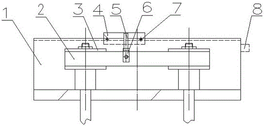
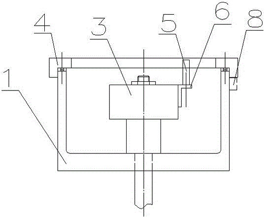
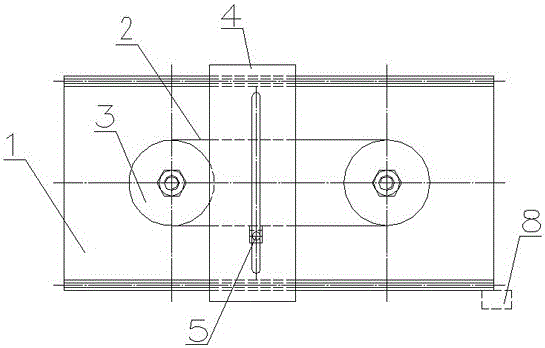
[0018] figure 1 , figure 2 with image 3 As shown, the specific implementation is as follows:
[0019] A tobacco leaf conveying device that can realize intermittent and uniform conveying includes a bracket 1, a conveyor belt 2, a conveyor belt wheel 3, a connecting piece 6, a pin 5 and a tobacco leaf conveying table 4. The conveyor belt wheel 3 is installed on the bracket 1 and driven by The shaft drives it to rotate, the conveyor belt 2 is sleeved on the conveyor pulley 3, the tobacco leaf conveying table 4 is slidably arranged on the bracket 1, and the tobacco leaf conveying table 4 is also provided with a through groove. The length of the groove is the same as the tobacco leaf conveying table 4. The direction of movement of the pin shaft 5 is vertical. One end of the pin shaft 5 is inserted into the through groove, and the other end is fixed on the conveyor belt 2 through the connecting piece 6, so as to realize the cyclical sliding of the tobacco conveying table 4 on the bracket 1 through the movement of the conveyor belt 2. One end of the unloaded tobacco leaves is also provided with a travel switch 8 for stopping the tobacco leaf conveying table 4 from working.
[0020] The tobacco leaf conveying table 4 is slidably arranged on the support 1 through rollers 7.
[0021] The drive shaft is connected with the power source to provide power for the entire conveying device.
[0022] The length of the said through groove is not less than the diameter of the conveyor pulley 3.
[0023] The conveyor belt wheel 3 rotates under the drive of the drive shaft, and the belt wheel drives the conveyor belt 2 to move. A connector 6 is installed on the conveyor belt, and a pin shaft 5 is installed on the connector. One end of the pin shaft 5 is just placed on the tobacco conveying table 4 In the long groove, the movement of the conveyor belt 2 drives the movement of the pin 5, and the pin 5 drives the movement of the tobacco conveying table 4. When the tobacco conveying table reaches the designated position, the contact installed on the tobacco conveying table touches the travel switch 8. At this time, the power is cut off and the conveying motor stops working. When the placing staff removes the tobacco leaves, press the contact switch again, the motor continues to run, and the pin 5 moves from one end of the groove to the other end, and continues to drive the tobacco conveying table back. At this time, the placing staff can place the tobacco leaves. When the loading staff at the other end reaches the other end of the conveyor, they load the tobacco leaves. When the tobacco leaves are transported to the other end again, at this time, if the placing staff has just completed the last placing The tobacco leaves delivered this time can continue to be placed. If the placing personnel did not place the last tobacco leaves, when the tobacco leaf conveyor 4 reaches the designated position, the stroke switch will be touched and the motor will stop running. This ensures that the tobacco leaves are not It will pile up at one end, which also ensures the safety of the staff.
[0024] The technical solutions and implementation manners listed in the present invention are not limitative, and the solutions that are equivalent or have the same effect as the technical solutions and implementation manners listed in the present invention are all within the protection scope of the present invention.

PUM

no PUM

Description & Claims & Application Information

We can also present the details of the Description, Claims and Application information to help users get a comprehensive understanding of the technical details of the patent, such as background art, summary of invention, brief description of drawings, description of embodiments, and other original content. On the other hand, users can also determine the specific scope of protection of the technology through the list of claims; as well as understand the changes in the life cycle of the technology with the presentation of the patent timeline. Login to view more.

Similar technology patents

Facsimile system based on Beidou information channel and facsimile data transmitting method

ActiveCN103391387ASecurity
Owner:HEFEI MAIWEI ELECTRONICS SCI & TECH CO LTD

Management method and system of national standard electronic seal

ActiveCN105429754ASecurity
Owner:西部安全认证中心有限责任公司

Large-scale dipolar antenna based NOMA downlink non-interfering transmission method

ActiveCN108768483Afree from delaySecurity
Owner:HARBIN INST OF TECH SHENZHEN GRADUATE SCHOOL

Classification and recommendation of technical efficacy words

  • Security
  • Reduce labor intensity

Method for intelligent automatic identification of transmission circuit parts

Owner:INFORMATION COMM COMPANY STATE GRID SHANDONG ELECTRIC POWER +2

City regional railway signal system and control method thereof

Owner:CHINA RAILWAY SIYUAN SURVEY & DESIGN GRP

Railway bearing intelligent on-line detection method and its device

InactiveCN101290265AReduce labor intensity
Owner:洛阳铭昊测控科技有限公司
Why Eureka
Try Eureka