Axial strainer

A tensioner, axial technology, applied in spring/shock absorber, spring/shock absorber design features, spring, etc., can solve problems such as not very ideal, high manufacturing and use costs, complex structure, etc., to achieve load The effect of stable operation, low cost and convenient use

Active Publication Date: 2015-10-28
CHANGTING NANCI ELECTRONICS
View PDF6 Cites 0 Cited by
  • Summary
  • Abstract
  • Description
  • Claims
  • Application Information

AI Technical Summary

Problems solved by technology

In order to solve this problem, there are also designs that use pneumatic compression, but the structure is complex, the cost of manufacture and use is high, and it is not very ideal

Method used


Image

  • Axial strainer
  • Axial strainer
  • Axial strainer

Examples


Embodiment 1

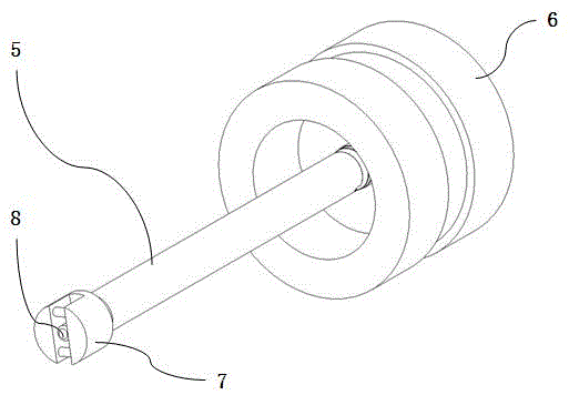
[0028] axial tensioner, see Figure 3 to Figure 9 and the background technology, it is characterized in that it consists of a fixed sleeve 1, a gear sleeve 2, a pin shaft 3 and at least two centrifugal pendulums 4; The gear sleeve hole 1-1 is provided with at least two swing grooves 1-2 on the peripheral wall of the fixed sleeve, and a pin hole 1-3 is provided at the radial position of one end of each swing groove; the outer surface of the gear sleeve There are at least two tooth row grooves 2-1 on the top; the centrifugal pendulum is in the shape of a long strip, one end is provided with a pin hole 4-1, and an engaging tooth row 4-2 is provided on the edge position; the tooth sleeve is inserted into the fixed sleeve Then put the centrifugal pendulum into the swing grooves of the fixed sleeve respectively, so that the meshing teeth of the centrifugal pendulum and the tooth row grooves on the gear sleeve mesh together, and finally insert the pin shaft into the pin hole of the f...

Embodiment 2

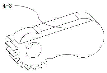
[0035] Application examples of axial tensioners, see Figure 10 The difference from Embodiment 1 is that the centrifugal pendulum of this embodiment is provided with a guide chamfer 4-3. When this embodiment is in working state, when the centrifugal pendulum is opened due to rotation, the air driven by the guide chamfer is blown to the motor and other equipment to assist the equipment to dissipate heat.

Embodiment 3

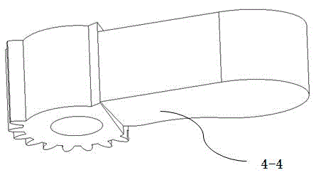
[0037] Application examples of axial tensioners, see Figure 11 , embodiment two and embodiment one. The difference from Embodiment 1 is that the centrifugal pendulum of this embodiment is provided with a guide curved surface 4-4. Its function is the same as that of the guide chamfer in embodiment 2, that is, when the centrifugal pendulum is opened due to rotation, the air driven by the guide curved surface is blown to equipment such as motors to assist these equipment to dissipate heat. However, the air volume driven by the guide curved surface is larger, but the manufacturing cost is higher than that of the guide chamfer.


PUM


Abstract

The invention particularly relates to a centrifugal type axial strainer which is composed of a fixing sleeve, a toothed sleeve, a pin shaft and at least two centrifugal pendulums. The fixing sleeve is in a shaft sleeve shape as a whole. A toothed sleeve hole is formed in the axial center of the fixing sleeve. At least two pendulum grooves are formed in the peripheral wall of the fixing sleeve, and one end of each pendulum groove is provided with pin holes in the radial direction. At least two tooth rank grooves are formed in the outer surface of the toothed sleeve. Each centrifugal pendulum is in a long-strip shape, the corresponding pin holes are formed in one end of each centrifugal pendulum, and an engaged tooth rank is arranged on the edge of each centrifugal pendulum. The toothed sleeve is inserted in the toothed sleeve hole of the fixing sleeve, then the centrifugal pendulums are placed in the pendulum grooves of the fixing sleeve, engaged teeth of the centrifugal pendulums and the tooth rank grooves in the toothed sleeve are made to be engaged together, and finally the pin shaft is inserted in the pin holes of the fixing sleeve and the pin holes of the centrifugal pendulums, so that the fixing sleeve, the toothed sleeve and the centrifugal pendulums are combined to form a whole. The axial strainer has the beneficial effects that the axial tension force of a rotation shaft can be increased, and a load is stable in operation.

Description

technical field [0001] The invention relates to a rotating shaft tensioner, in particular to a centrifugal axial tensioner, which can be widely used in processing equipment such as cutting, grinding and polishing of stone, steel and other materials. Background technique [0002] In the materials processing industry, see figure 1 and figure 2 , the material needs to be ground and polished. It is usually necessary to fix the grinding wheel 6 on the rotating shaft 5 . When grinding grooves or different patterns on the surface of the material, it is necessary to require the grinding wheel not to move axially and shake up and down, so as to meet the requirements of precision machining. In order to prevent the grinding wheel from vibrating during processing, a common practice is to set a fixed stop ring 10-1 integrated with the central shaft on the central shaft 10 of the grinding wheel, and then insert the central shaft into the center hole of the grinding wheel to make the g...

Claims


Application Information

Patent Timeline
IPC IPC(8): F16F15/00
CPCF16F15/00F16F2230/0011
Inventor 许友提徐晓辉黄文龙
Owner CHANGTING NANCI ELECTRONICS
Why Eureka
Try Eureka