Unmanned aerial vehicle visible light and infrared image target positioning method under large squint angle

A technology of target positioning and infrared images, which is applied in the field of remote sensing image processing to achieve the effect of small calculation and high precision

Active Publication Date: 2015-10-28
BEIHANG UNIV
View PDF6 Cites 18 Cited by
  • Summary
  • Abstract
  • Description
  • Claims
  • Application Information

AI Technical Summary

Problems solved by technology

[0006] The purpose of the present invention is to solve the problem of target positioning under the condition of large oblique angle of view of UAV, and propose a method for target positioning of visible light and infrared i

Method used


Image

  • Unmanned aerial vehicle visible light and infrared image target positioning method under large squint angle
  • Unmanned aerial vehicle visible light and infrared image target positioning method under large squint angle
  • Unmanned aerial vehicle visible light and infrared image target positioning method under large squint angle

Examples


Embodiment Construction

[0026] The present invention will be further described in detail with reference to the accompanying drawings and embodiments.

[0027] The present invention is a target positioning method of UAV visible light and infrared images under a large oblique viewing angle, the process is as follows Figure 8 As shown, the specific implementation steps are as follows:

[0028] The first step: Target positioning of visible light and infrared images based on imaging model;

[0029] Specifically:

[0030] (1) Geometry correction of reconnaissance image system based on coordinate system conversion;

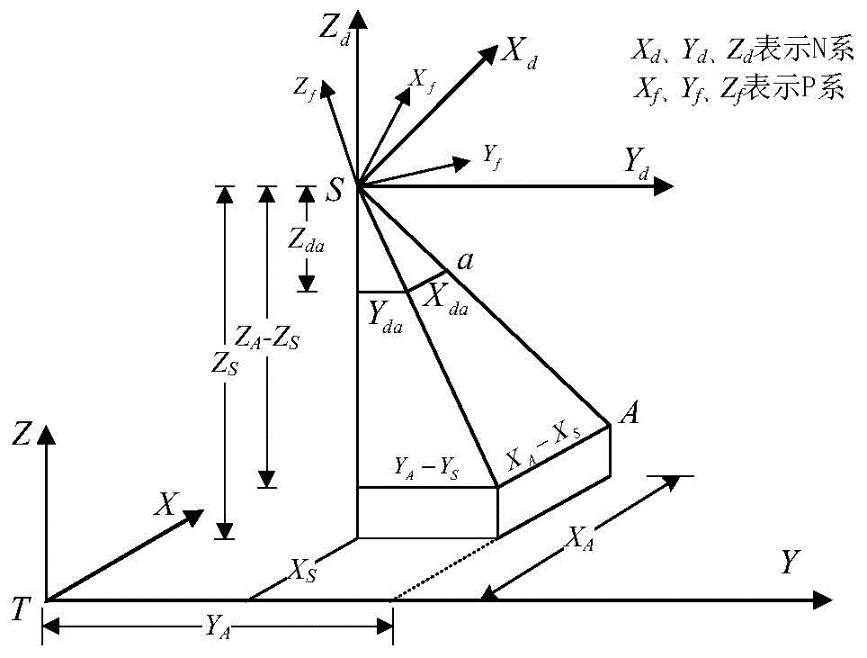
[0031] The process of image correction is actually the process of converting the image coordinate system to the earth coordinate system.

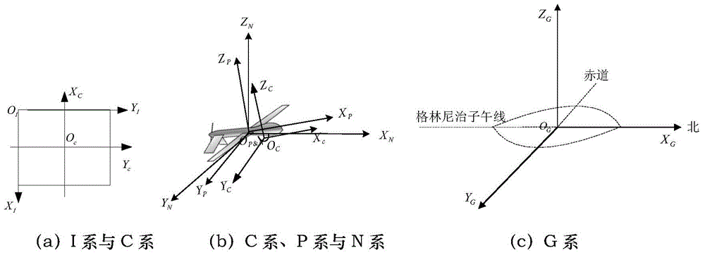
[0032] To perform system-level geometric correction based on the central projection imaging model, it is necessary to establish the transformation relationship between each coordinate system. The transformation from the image plane to the space Cartesia...


PUM


Abstract

The invention discloses an unmanned aerial vehicle visible light and infrared image target positioning method under a large squint angle. The method includes the steps that firstly, target positioning is performed based on visible light and infrared images of an imaging model; secondly, target positioning error characteristic extraction and representation are performed under various-factor influences; thirdly, target positioning error prediction and compensation are performed at variable heights and the large squint angle. Under the condition of the large squint angle, the unmanned aerial vehicle target positioning precision can be effectively improved. The target positioning and error compensation method is small in calculation amount and can meet the real-time requirement of airborne computation. The method is suitable for target positioning application of images, conforming to the central projection imaging model, such as the visible light images and the infrared images.

Description

technical field [0001] The invention belongs to the technical field of remote sensing image processing, and in particular relates to a target positioning method of visible light and infrared images of an unmanned aerial vehicle under a large oblique viewing angle. Background technique [0002] As an advanced reconnaissance data processing technology, UAV target positioning has important application value in both civilian and military fields. [0003] There are three main target positioning methods based on UAV reconnaissance images: 1. Target positioning based on image matching mode, 2. Target positioning based on imaging model, 3. Target positioning method based on space rendezvous. Method 1 has high precision, time-consuming calculation, and relies on control points or orthophotos, which is difficult for real-time processing and large-scale application. Method 2, the amount of calculation is small, but the positioning accuracy is easily affected by factors such as paramet...

Claims


Application Information

Patent Timeline
IPC IPC(8): G01C25/00G01C11/34
CPCG01C11/34G01C25/00
Inventor 李红光丁文锐刘家良
Owner BEIHANG UNIV
Why Eureka
Try Eureka