
Azimuth-equivalent delay difference passive positioning method ofdouble circular arrays

A passive positioning and equivalent time delay technology, applied in positioning, measuring devices, instruments, etc., can solve the problems that the time delay difference estimation results are susceptible to noise interference, affecting positioning accuracy, equipment complexity and system cost increase, etc., to achieve Improve the accuracy of time delay estimation, improve positioning accuracy, and save costs

Active Publication Date: 2020-06-23
HARBIN ENG UNIV
View PDF10 Cites 4 Cited by
  • Summary
  • Abstract
  • Description
  • Claims
  • Application Information

AI Technical Summary

Problems solved by technology

[0008] When the traditional azimuth-delay positioning method calculates the delay difference information, it only uses the received data of the array elements at the reference position of the array, and does not use all the array element data of the array, which makes the delay difference estimation results extremely susceptible to noise interference, which in turn affects positioning accuracy
In terms of array structure, for a special array structure such as a uniform circular array, a reference array element is usually added at the center of the array when the delay difference is estimated, which greatly increases the complexity of the equipment and the cost of the system.

Method used


Image

  • Azimuth-equivalent delay difference passive positioning method ofdouble circular arrays
  • Azimuth-equivalent delay difference passive positioning method ofdouble circular arrays
  • Azimuth-equivalent delay difference passive positioning method ofdouble circular arrays

Examples


Embodiment Construction

[0036] The present invention will be further described in detail below in conjunction with the accompanying drawings and specific embodiments.

[0037] The technical solution adopted by the present invention to solve its technical problems comprises the following steps:

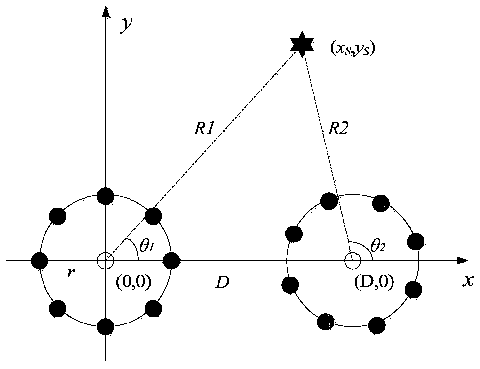
[0038] Step 1, establish a dual-array positioning space model, the number of elements of the two uniform circular arrays is both M (M is an even number), the center of the circular array is the array reference point, the radius of the circular array is r, and the distance between the two reference points is D. The direction of the line connecting the two reference points is the direction of the x-axis, and the direction of the vertical line of the line is the direction of the y-axis to establish a Cartesian coordinate system, then the coordinates of the reference points of the two circular arrays are respectively (x 1 ,y 1 ),(x 2 ,y 2 ), at (x s ,y s ) coordinates of the target sends a signal s(t), and t...


PUM


Abstract

The invention provides an azimuth-equivalent delay difference passive positioning method of double circular arrays. The method comprises the steps: firstly building a double-array space positioning model, and obtaining output data x1 (t) of each array element of two circular arrays, wherein l equals to1 and 2; calculating azimuth angles theta1 and theta2 of a target relative to the two array reference points by utilizing a spatial spectrum estimation algorithm; calculating a time delay difference tauij between the ith array element of the circular array 1 and the jth array element of the circular array 2 by using a time delay estimation algorithm, and calculating an equivalent time delay difference taue by using the tauij; and substituting the azimuth angles theta1 and theta2 and the equivalent delay difference taue into an azimuth-equivalent delay difference positioning formula, and obtaining a distance R1R2 from the target to each array reference point and a coordinate position coordinate (xs, ys) of the target. Reference array elements are prevented from being added to a center of the uniform circular array, an array structure is simplified, system cost is saved, meanwhile, array redundant information is utilized, time delay estimation precision is improved, and then target positioning precision is increased.

Description

technical field [0001] The invention relates to an azimuth-equivalent time delay difference passive positioning method of a double circular array, which belongs to the field of target passive positioning. Background technique [0002] According to the different types of information used, dual-array passive positioning technology can be divided into pure azimuth positioning and azimuth-delay difference positioning methods. In the azimuth-only positioning method, the two arrays calculate the azimuth angle of the same target respectively, and use the triangular relationship to estimate the distance, and then obtain the target position coordinates. The azimuth cross positioning has a wide range of applications, but the positioning error is very sensitive to the azimuth accuracy. [0003] The azimuth-delay difference positioning method is an improved algorithm for azimuth cross positioning, which utilizes the spatial coherence between the two array elements. When the coherence ...

Claims


Application Information

Patent Timeline
Patent Type & Authority Applications(China)
IPC IPC(8): G01S5/02G01S5/04G01S5/12
CPCG01S5/0257G01S5/04G01S5/12
Inventor 时胜国张旭杨德森朱中锐方尔正莫世奇
Owner HARBIN ENG UNIV
Learn More