Friction testing stand

A test bench, manual wheel technology, applied in measuring devices, instruments, mechanical devices, etc., to achieve the effects of simple operation, high degree of automation, and compact structure

Active Publication Date: 2015-10-28
NAVAL UNIV OF ENG PLA
View PDF6 Cites 2 Cited by
  • Summary
  • Abstract
  • Description
  • Claims
  • Application Information

AI Technical Summary

Benefits of technology

This new technology helps reduce noise from measuring frictional properties by eliminating any external factors that could affect how well it works when tested under varying temperatures or pressures. Additionally, this innovative design allows for precise testing of both dry-frigerated rubber (DD) and wet-lubled rubbers (WD).

Problems solved by technology

This patented technical problem addressed in this patents relates to improving the accuracy and reliance with measurement of frictional behavior during testing processes that involve moving parts or objects under high pressure conditions such as ship-board systems.

Method used


Image

  • Friction testing stand
  • Friction testing stand
  • Friction testing stand

Examples


Embodiment Construction

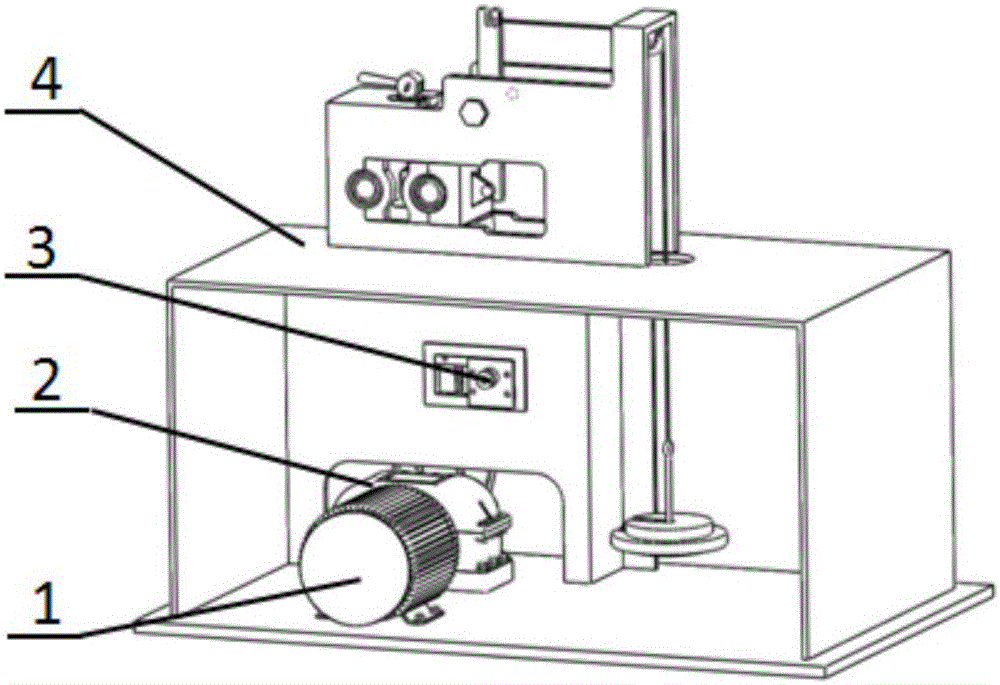
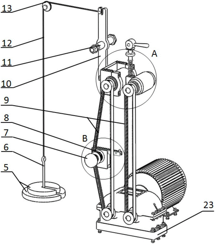
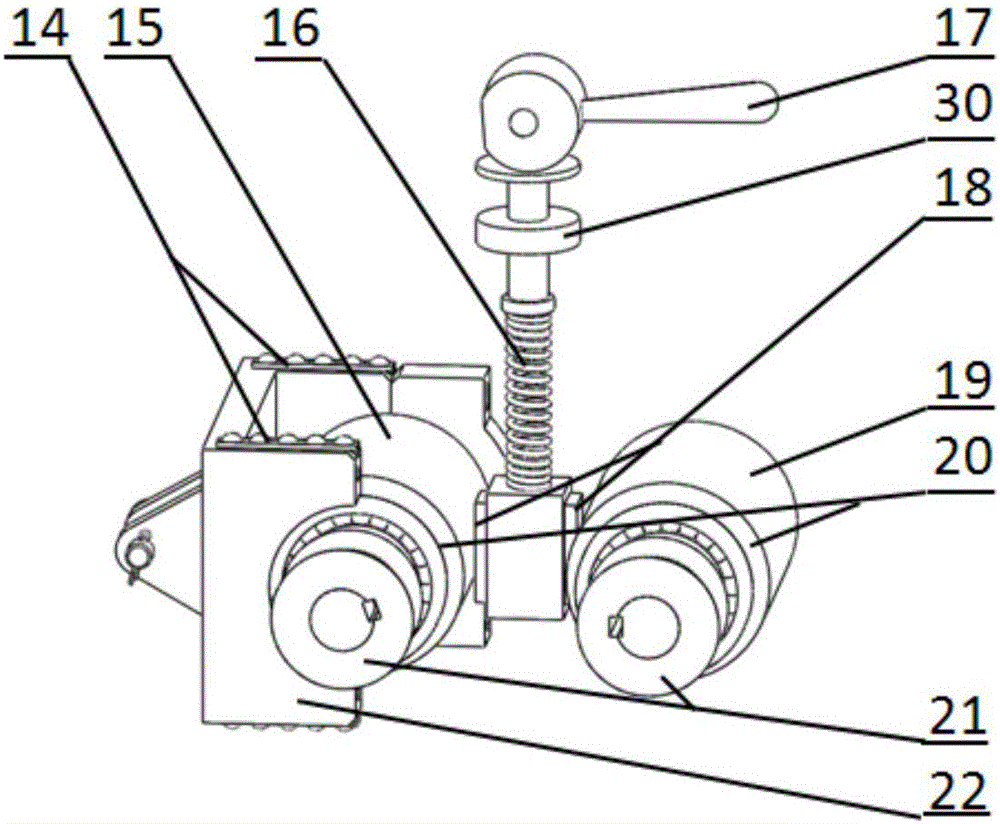
[0025] The present invention is made up of frame 4, vibration isolator 23, power system, loading system, test system, control and data processing system and auxiliary system. The auxiliary system is mainly composed of the timing belt tensioning mechanism 3, the sample shaft quick change mechanism, the spray system, the lubrication system, and the temperature detection system. Frame 4 supports all components of the friction test bench. The test system takes the sensor and the sample as a whole to directly measure the motion information of the sample; the control and data processing system solves the characteristics of the friction force according to the dynamic equation of the test system, and then solves the friction coefficient and friction vibration characteristics of the sample.

[0026] The present invention will be described in detail below with reference to the accompanying drawings.

[0027] refer to figure 1 , figure 2 with image 3 , the servo motor 1 is connecte...


PUM


Abstract

The invention relates to a friction testing stand which is composed of a rack, a vibration isolator, a power system testing system, a control and data processing system and an auxiliary system, etc. The auxiliary system is composed of a synchronous belt tensioning mechanism, a spraying system, a temperature measuring system and the like. The rack supports all devices. A servo motor synchronously drives first and second specimen shafts to rotate at the same speed and in the reverse direction through two rotational motions at the same rotational speed and in the reverse direction that are outputted by a gear case. By gravity horizontal loading of a counterweight on the first specimen shaft through a fixed pulley and a stressing lever, the first specimen shaft presses a test-piece and the second specimen shaft tightly under the gravity loading so as to form two identical frictional forces, and the test-piece vibrates under the action of the two frictional forces. Displacement changes of the test-piece are calculated through detecting force variation of a force sensor, and frictional coefficient and frictional vibration characteristics of a sample material are calculated. Interference generated by vibration of the testing system can be eliminated, and testing is accurate. The friction testing stand has a compact structure and is simple to operate.

Description


Claims


Application Information

Patent Timeline
Owner NAVAL UNIV OF ENG PLA
Why Eureka
Try Eureka